
Zoom out Search Issue


IEEE SIGNAL PROCESSING MAGAZINE [84] MARCH 2015
positions of the loudspeakers and the matching points within
sound zones must be chosen judiciously for good reproduc-
tion performance. Representing sound fields in the wave
domain or mode domain as in (S1) in “Wave-Domain Sound
Field Representation” can provide physical insights into these
critical issues [15]. Dimensionality analysis tells us that for
PM over
Q sound zones, the number of loudspeakers required
is determined by the upper frequency or wave number k of
operation, the number of sound zones, and the size of each
sound zone [15]. Here we assume that each sound zone is a
circle or sphere of radius
r
0
located at the origin O
q
as shown
in Figure 1, although without loss of generality each sound
zone could be of arbitrary shape. The minimum number
L
is about ()Qkr21
0
+ for two-dimensional (2-D) reproduction
and ()Qkr 1
0
2
+ for three-dimensional (3-D) reproduction,
respectively [4].
DISCUSSION
Practical Implementation
When a small number of loudspeakers are used, for example, three
speakers used in a mobile device, current personal audio systems
can only achieve limited performance, i.e.,
~10 dB contrast level
between bright and dark zones [7]. An array of nine sources has
been implemented for personal audio systems in televisions and
personal computers, in an anechoic chamber achieving over 19 dB
contrast under ideal conditions [6]. However, in terms of practical
implementation in a car cabin, Cheer et al. [8] demonstrated that
the optimized level of acoustic contrast obtained from the ACC
method may not be achieved because of errors and uncertainties
and the least-squares-based PM approach may provide a more
robust solution. In addition, multizone reproduction is fundamen-
tally constrained whenever attempting to reproduce a sound field
in the bright zone that is directed to or obscured by another zone.
This is known as the occlusion problem [11], [12].
Loudspeaker Positions
Using the compressive sensing idea, the formulation of multizone
sound field reproduction can be regularized with the
1
, norm of
WAVE-DOMAIN SOUND FIELD REPRESENTATION
The Helmholtz wave equation can be solved to express
any sound field as a weighted sum of basis functions,
(, ) ( ) (, ),xxp
n
n
n
1
~a~b~=
3
=
/
(S1)
where ( )w
n
a are sound field coefficients corresponding
to mode index ,n (, )x
n
b~ are basis functions with the
orthogonality property
,(,)(,)().xxxdw
*
nm n m nnm
C
_GHbb b ~b ~ p d=
#
The sound field within a control region C can be repre-
sented using a finite number of basis functions, i.e.,
[, ]n 1 N! and ( ) ,w
nn
n
GHpb
b= is the strength of each
mode over the control zone.
The modal basis functions for source distributions and
sound fields expressed in cylindrical coordinates and spheri-
cal coordinates can be written as [17]
(, ) ( ) ( ) ( )x exppkriJ
()
N
N
2
2
D
D
~a~ oz=
o
o
o
=-
/
(S2a)
(, ) ( ) ( ) (, ),xpkrYJ
()
N
3
0
3
D
D
~a~ iz=
o
n
no
o
o
o
o
n
=-=
//
(S2b)
where ( )exp $ and ()Y $
o
n
are complex exponentials and spheri-
cal harmonics, respectively and ( )krJ
()2D
o
and ( )krJ
()3D
o
are
functions representing the 2-D and 3-D mode amplitudes at
radius ,r respectively. Given the radius of the control region
r
0
, wave number ,k and the truncation number Nkr
0
. [4],
we have the following dimensionality results: kr21N
D20
=+
and .
()
kr 1N
D30
2
=+
This gives the Nyquist sampling condi-
tion for a uniform circular array )(M N
D2
$ and a spherical
array ),(M N
D3
$ respectively.
100
80
60
40
20
0
–40
–200
–100
100
0
–30
–20
–10
0
10MSE in Bright Zone (dB)
Array Effort (dB)
Acoustic Contrast (dB)
3
2
1
0
–1
–2
–3
–3 –2 –1 0 1 2 3
–1
–0.8
–0.6
–0.4
–0.2
0.2
0.4
0.6
0.8
1
0
y (m)
x (m)
(a) (b)
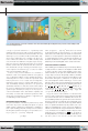
[FIG2] A plane wave of 500 Hz from 45˚ is reproduced in the bright zone (red circle) using PM while deadening the sound in the dark
zone (blue circle) using 30 loudspeakers placed on a circle of radius
,R 3m= and each zone is of radius .r 06m= as shown in (a). (b)
The acoustic contrast versus the array effort and the mean-square reproduction error in the bright zone using the ACC method (blue
line) and the PM method (red line).
Previous Page | Contents | Zoom in | Zoom out | Front Cover | Search Issue | Next Page
q
q
M
M
q
q
M
M
q
M
THE WORLD’S NEWSSTAND
®
Previous Page | Contents | Zoom in | Zoom out | Front Cover | Search Issue | Next Page
q
q
M
M
q
q
M
M
q
M
THE WORLD’S NEWSSTAND
®