
Zoom out Search Issue


IEEE SIGNAL PROCESSING MAGAZINE [82] MARCH 2015
concept of a personal sound zone, i.e., reproducing sound
within a desired region of space with a reduced sound level else-
where. Microsoft researchers later demonstrated their “Personal
Audio Space” project at Microsoft Research TechFest 2007,
where a linear loudspeaker array consisting of 16 drivers was
used to enhance the sound in one area while canceling sound
waves in another area within the same physical space. By step-
ping even a few paces outside the target region, users reported
that they could not hear the reproduced music. Researchers fur-
ther extended this concept to develop personal audio for per-
sonal computers and televisions [6], as well as for mobile
devices [7] and automobile cabins [8].
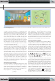
A way to create personal sound zones is to formulate a
multizone sound control problem within the same physical
space as illustrated in Figure 1. Here, multiple microphones
and loudspeakers are used to control the reproduced sound
fields. A preference is to use a single array of loudspeakers
rather than separate arrays for each zone. This improves free-
dom and flexibility, allowing sound zones to be positioned
dynamically and listeners to freely move between zones. When
the system is implemented in reverberant enclosures, loud-
speaker designs and audio processing are two key aspects to
control sound radiation and to deal with the complexity and
uncertainty associated with sound field reproduction. This
article aims at reviewing these techniques to support the goal
of establishing personal sound zones.
MULTIZONE SOUND CONTROL
In a general formulation, sound fields are produced over
Q sound
zones. Here M pressure controlling microphones are placed
within each zone so that the zone sound fields are controlled by a
total of
QM matching points. The sound pressures measured at
the microphone positions in each zone q are represented as a vec-
tor ()[( ), , ]xpx pp
,,,, q Mqq
T
1
f ~~= and given by
,pHg
qq
= (1)
where [( , ), , ( , )]gy ygg
L
T
1
f~~= denotes the vector of loud-
speaker driving signals at a given frequency
~ to create personal
audio sound scenes and H
q
represents a matrix of acoustic transfer
functions (or acoustic impedances) between the loudspeaker driv-
ers and the microphones in zone
.q Sound control techniques can
broadly be classified into two categories, acoustic contrast control
(ACC) and pressure matching (PM), and we consider each in turn.
ACOUSTIC CONTRAST CONTROL
Choi and Kim [9] first formulated the personal audio problem by
creating two kinds of sound zones: the bright zone within which
we want to reproduce certain sounds with high acoustic energy,
and the dark zone (or the quiet zone) within which the acoustic
energy is kept at a low level. The principle of ACC is to maximize
the contrast in the acoustic energy between the bright zone and
the dark zone. Among the
Q sound zones, we specify the first
zone as the bright zone and the remaining Q 1- zones as the
dark zones. The acoustic energy in the bright zone is defined from
the sound pressures measured at the
M matching points, that is
pHgE
22
bb b
== with HH
1b
= and · denoting the
2
,
norm. Similarly, the acoustic energy in the dark zones is repre-
sented as
pHgE
22
dd d
== with [ , , ]HH H
H
Q
H
H
2
d
f= and
()
H
$ represents the Hermitian transpose.
In [9], the acoustic contrast, defined as a ratio between the
average acoustic potential energy density produced in the bright
zone to that in the dark zones, is maximized. The acoustic con-
trast maximizing method may perform well over the dark zones
but may be unrobust to providing the desired maximum energy
in the bright zone. To ensure the sound energy within different
zones are optimized simultaneously, the problem can be refor-
mulated as maximizing the acoustic energy in the bright zone
with the constraint that the energy in the dark zone is limited to
a very small value
.D
0
In addition, a limit is imposed on the
loudspeaker power consumption, i.e., ,g E
2
0
# also known as
the array effort. These constraints ensure that sound leakage out-
side the
Q zones is not excessive and also that realized
g(y
1
) g(y
2
)
g(y
L
)
g(y
l
)
R
H
Q
O
q
r
o
Zone 1
Zone q
Zone Q
(a) (b)
[FIG1]
(a) An illustration of personal sound zones in an office environment. (b) A loudspeaker array is used to create multiple sound
zones for multiple listeners.
Previous Page | Contents | Zoom in | Zoom out | Front Cover | Search Issue | Next Page
q
q
M
M
q
q
M
M
q
M
THE WORLD’S NEWSSTAND
®
Previous Page | Contents | Zoom in | Zoom out | Front Cover | Search Issue | Next Page
q
q
M
M
q
q
M
M
q
M
THE WORLD’S NEWSSTAND
®