
Zoom out Search Issue


IEEE SIGNAL PROCESSING MAGAZINE [38] MARCH 2015
purpose, we adjust the gains ( , )knG
i
and ( )kQ
i
in (3) depending
on the application and as desired by the user. For spatial audio ren-
dering,
(, )knG
i
and ( )kQ
i
are used to generate the different
output channels for a given reproduction setup, whereas for signal
enhancement applications, (, )knG
i
and ( )kQ
i
are used to realize
parametric filters that extract a signal of the desired sound source
while reducing undesired and diffuse sounds. In all cases, the gains
are computed using the estimated sound field parameters, and are
used to obtain a weighted sum of the estimated direct and diffuse
components, as given by (3). In the following, we present an over-
view of different applications in which the output signals are
obtained using this approach.
SPATIAL AUDIO COMMUNICATION
Using spatial audio communication, we can allow participants in
different locations to communicate with each other in a natural
way. The sound acquisition and reproduction should provide good
speech intelligibility, as well as a natural and immersive sound.
Spatial cues are highly beneficial for understanding speech of a
desired talker in multitalker and adverse listening situations [18].
Therefore, accurate spatial sound reproduction is expected to
enable the human brain to better segregate spatially distributed
sounds, which in turn could lead to better speech intelligibility. In
addition, flexible spatial selectivity offered by adjusting the time-
frequency dependent gains of the transmitted signals based on the
geometric side information, enables the listener to focus even bet-
ter on one or more talkers. These two features make the parametric
methods particularly suited to immersive audio-video teleconfer-
encing, where hands-free communication is typically desired. In
hands-free communication (that is without any tethered micro-
phones), the main challenge is to ensure the high quality of the
reproduced audio signals captured from distance, and to recreate
plausible spatial cues at the listeners ears. Note that for full-duplex
communication, multichannel acoustic echo control would addi-
tionally be required to remove the acoustic coupling between the
loudspeakers and the microphones [5]. However, the acoustic echo
cancelation problem is beyond the scope of this article.
Let us consider such a teleconferencing scenario with two
active talkers at the recording side, as illustrated in Figure 5. The
goal is to recreate the spatial cues from the recording side at the lis-
tener side over an arbitrary, user-defined multichannel loudspeaker
setup. At the recording side, one of the talkers is sitting on a couch
located in front of a TV screen at a distance of 1.5 m and angle 10°
with respect to array broadside direction, while the other is located
to the left (at –20°) at roughly the same distance. The TV has a
built-in camera and is equipped with a six-element linear array
with inter-microphone spacing of 2.5 cm that captures the rever-
berant speech and noise (with SNR = 45 dB); the reverberation
time is 350 ms. At the reproduction side, the
ith loudspeaker signal
is obtained as a weighted sum of the direct and diffuse signals, as
given by (3). To recreate the original spatial impression of the
recording side (without additional sound scene manipulation), the
following gains suffice
(, ) (, , )kn knGP
ii
i= and ( ) 1,kQ
i
=
where (, , )knP
i
i is the panning gain for reproducing the direct
sound from the correct direction, which depends on the selected
panning scheme and the loudspeaker setup. As an example, the
vector-base amplitude panning (VBAP) [28] gain factors for a stereo
reproduction system with loudspeakers positioned at
30! c are
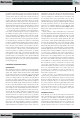
[FIG6] The results in a communication scenario: (a) applied gain
functions, (b) spectrogram of the input signal, (c) estimated
directions of arrival, (d) gains applied to the direct sound for the
right loudspeaker channel, (e) spectrogram of the right
loudspeaker signal, and (f) spectrogram of the right loudspeaker
signal after applying ()B
i
defined in (a).
Input Signal
(a)
Frequency [kHz]
100 200
0
2
4
6
–60
–40
–20
0
0
–40
–20
0
20
40
60
0
Right Loudspeaker Signal
0
–60
–40
–20
0
Right Loudspeaker Signal with Directional Gain
0 –60
–40
–20
0
Frequency [kHz]
2
4
6
Frequency [kHz]
2
4
6
Frequency [kHz]
2
4
6
Frequency [kHz]
2
4
6
–60 –30 0 30 60
0
0.5
1
Direction of Arrival [°]
Direction of Arrival [°]
Gain Functions
P
left
(θ )
P
right
(θ )
B(θ )
Time Frame Index
100 200
Time Frame Index
100 200
Time Frame Index
100 200
Time Frame Index
100 200
Time Frame Index
(b)
(c)
(d)
(e)
(f)
Right Loudspeaker Gain
0
0.5
1
Previous Page | Contents | Zoom in | Zoom out | Front Cover | Search Issue | Next Page
q
q
M
M
q
q
M
M
q
M
THE WORLD’S NEWSSTAND
®
Previous Page | Contents | Zoom in | Zoom out | Front Cover | Search Issue | Next Page
q
q
M
M
q
q
M
M
q
M
THE WORLD’S NEWSSTAND
®