FX-DS110-PCC FLEXLAN-DS110 Series PC Card User’s Guide
Copyright Copyright 2001 CONTEC Co., LTD. ALL RIGHTS RESERVED No part of this document may be copied or reproduced in any form by any means without prior written consent of CONTEC Co., LTD. CONTEC Co., LTD. makes no commitment to update or keep current the information contained in this document. The information in this document is subject to change without notice. All relevant issues have been considered in the preparation of this document.
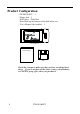
Product Configuration - FX-DS110-PCC …1 - Floppy disk …1 Disk: driver - UtilitySoft Note: Back up the contents of the disk before use. - User’s Manual (this booklet)…1 WIRELESS LAN CARD FX-DS110-PCC User's Manual Disk User's Manual Check the contents to make sure that you have everything listed above. If you do not have all the items, contact your distributor or CONTEC group office where you purchased.
Table of Contents Copyright ............................................................................i Trademarks ........................................................................i Product Configuration ..................................................... ii 1. Introduction ............................................................. 1 Features.........................................................................1 Terminology/Abbreviations...........................................
4. Installation of a driver ............................................ 21 Driver software ...............................................................21 Installing for Windows Me .............................................22 Installing for Windows 98...............................................23 Installing for Windows 95...............................................24 Installing for Windows 2000...........................................26 Installing for Windows NT ...............................
List of Figures Figure 2.1. Component Locations............................................... 7 Figure 2.2. User unit..................................................................11 Figure 2.3. Access point ............................................................11 Figure 2.4. Micro access point.................................................. 12 Figure 3.1. Infrastructure Mode................................................ 18 Figure 3.2. ADHOC Mode ....................................
vi FX-DS110-PCC
Introduction 1. Introduction Thank you for purchasing the FLEXLAN-DS110series PC-Card FX-DS110-PCC. This product is a wireless LAN PC card that operates in the 2.4 GHz band using direct sequence spread spectrum (DSSS). It complies with the IEEE 802.11B wireless LAN standard and can use 1 to 11 or 13 channels. This document explains how to use the FX-DS110-PCC. Be sure to read it carefully so that you can use the product correctly. Features IEEE 802.11b compliant wireless LAN in the 2.
Introduction channels available increased to 11(FCC model) or 13(CE model). Using different channels for adjacent wireless networks prevents radio interference, thereby improving the throughputs of the network. Capable of inter-channel roaming PC Card (TYPE II) compliant interface Using an option of the PC-CARD(PC)H or either the FX-PCI-EXT2 or FX-PCI-WOL allows the FX-DS110-PCC to be connected to an ISA or PCI bus slot.
Introduction Limited One-Year Warranty CONTEC Interface boards are warranted by CONTEC Co., LTD. to be free from defects in material and workmanship for up to one year from the date of purchase by the original purchaser. Repair will be free of charge only when this device is returned freight prepaid with a copy of the original invoice and a Return Merchandise Authorization to the distributor or the CONTEC group office, from which it was purchased.
Introduction Handling Precautions Take the following precautions when handling this product. - Before inserting this PC card, check the configuration of the PC card slot and make sure the card is oriented properly. Improper insertion may result in a bad connection or damage to the card or connector. - Do not apply excessive force to the PC card connector as doing so may result in a bad connection or damage to the card or connector.
Introduction Notes on Radio Interference The frequency band used by this product covers the operating frequencies of mobile-identification local radio stations (requiring the license) and specific low-power radio stations (requiring no license) as well as industrial, scientific, and medical equipment such as microwave ovens. 1. Before using this product, make sure that there is no mobileidentification local radio station or specific low-power radio station operating near the product. 2.
Introduction About the Manual This manual consists of the following chapters: 6 Chapter 1 Introduction Chapter 2 Overview Gives an overview of the FX-DS110-PCC. Chapter 3 Installation of a hardware Describes how to install the FX-DS110-PCC on your PC. Chapter 4 Installation of a driver Describes the contents of the driver floppy disk for the FX-DS110-PCC and the procedures for installing the driver.
Overview 2. Overview The FX-DS110-PCC is the product to be plugged into a PC Card slot to construct a wireless network. This chapter provides an overview of this product. Component Locations WIRELESS LAN CARD PC-Card Interface LED Indicators Flat antenna Figure 2.1. Component Locations Flat antenna This product transmits and receives radio waves via the antenna. Since the antenna is connector-coupled with the body of the FX-DS110-PCC, an optional antenna can be connected.
Overview LED Indicators The FX-DS110-PCC has two LEDs to indicate its operation status. The LEDs appear as follows when the PC Card is operating normally. Table 2.1.
Overview List of Options Desktop PC adapter The desktop PC adapter allows the user unit (FX-DS110-PCC) to be used on a desktop PC. There are three types of desktop PC adapters available: PC-CARD(PC)H as the ISA bus adapter, FX-PCI-EXT2 as the PCI bus adapter, and FX-PCI-WOL as the PCI bus adapter for Wake-on-LAN. PC-CARD(PC)H FX-PCI-EXT2 FX-PCI-WOL Antenna An extension antenna can be used depending on the operating environment and application.
Overview Outline of the FLEXLAN-DS110 series The FLEXLAN-DS110 series is a line of three items: the user unit and two types of access points. Features of the FLEXLAN-DS110 series IEEE 802.11b compliant, 2.4 GHz band wireless LAN This product is a wireless LAN device operating in the 2.4 GHz band, which can be used with no license. It complies with the IEEE 802.11b wireless LAN standard.
Overview Production introduction to the FLEXLAN-DS110 series User unit (FX-DS110-PCC) The user unit is equivalent to the LAN card for a wired LAN. plugged into the PC for use. It is The FX-DS110-PCC is the PC Card (TYPE II) type. The PC-CARD(PC)H, FX-PCI-EXT2, and FX-PCI-WOL are the ISA bus adapter, PCI bus adapter, and PCI bus adapter for Wake-onLAN, respectively, available as options. WIREL ES S L AN CARD FX-DS110-PCC Figure 2.2.
Overview Micro access point (FX-DS110-APL) The micro access point can be used as an access point in a smallscale wireless LAN system or as a station (between the Ethernet and wireless converter). You can construct a wireless LAN easily by connecting the micro access point to an Ethernet built-in device with an UTP cable. RX LINK WRX WL INK POWER FX-DS110-APL Figure 2.4.
Installation of a driver 3. Installation of a driver This chapter describes how to install the FX-DS110-PCC on your PC. Plugging the FX-DS110-PCC Follow the procedure below to plug the FX-DS110-PCC on your PC. To use the PC Card under Windows NT 4.0, shut down the PC before plugging it in the PC card slot. (1) Make sure that your PC has a PC Card (TYPE II) slot. (2) Plug the FX-DS110-PCC into the PC Card slot with the inserting direction mark s face up.
Installation of a driver Unplugging the FX-DS110-PCC The system may run out of control if you unplug the FX-DS110-PCC with Windows 95, 98, or 2000 running without following the procedure below. If your PC is under Windows NT 4.0, shut down the PC before unplugging the PC Card. (1) In Windows, open the Start Menu and select “Settings” and then “Control Panel”.
Installation of a driver Installation in a network This section describes how to install the FLEXLAN-DS110 series to construct a network with improved performance and discusses the general features and radio characteristics of the wireless LAN as well as the guidelines for constructing the network. Features of the wireless network The most prominent feature of the wireless network is that it uses radio waves as its medium, eliminating the need for cabling.
Installation of a driver Obstacles blocking radio waves include metal walls and walls containing a metal firewall. RSSI (Receive Signal Strength Indication) utility is available as a means of knowing the signal strength of an incoming radio wave. Placing this product for a greater RSSI value makes the communication state more stable.
Installation of a driver Constructing a network Given below are the guidelines and notes on constructing a network: (1) The operating distance of the FX-DS110-PCC between the AP and user unit is about 150 m in indoor space with no obstacle or about 50 m in indoor space with few obstacles. (2) This product enables communication via a total of 11(FCC model) or 13(CE model) channels from channels 1 to 11 or 13.
Installation of a driver of 3 m between each AP and user unit. (7) When this product is used in the ADHOC (Simple) Mode, network performance is degraded unless all the terminals exist within the operating range for communication. (See "Hidden Terminal Problem” in Chapter 7.) Operation of the FLEXLAN-DS110 This section describes the types of networks configurable with the FX-DS110-PCC, using basic examples.
Installation of a driver Figure 3.1. Infrastructure Mode ADHOC (Simple) Mode In this mode, all wireless terminals communicate with one another on a par basis. Since wireless terminals communicate directly with each other, the most part of setup at installation is not required and faster communication can be expected than in the APcentralized configuration. When installing the terminals, place them all within their operating distance for communication (to prevent the hidden terminal problem).
Installation of a driver 20 FX-DS110-PCC
Installation of a driver 4. Installation of a driver This chapter shows the contents of the driver floppy disk for the FX-DS110-PCC and describes the procedure for installing the driver. Before proceeding to install the driver, read Chapter 2 “Installing the Hardware” to plug the FX-D110-PCC on your PC. This chapter contains the driver installation procedures for Windows Me, Windows 98, Windows 95, Windows 2000, and for Windows NT 4.0.
Installation of a driver Installing for Windows Me (1) Windows Me detects the FX-DS110-PCC as a new piece of hardware at startup and invokes the “Add New Hardware wizard” with its dialog box. (2) Insert the “Driver Disk #1” floppy disk into the floppy disk drive. This procedure assumes the floppy disk drive as drive A. (3) Select “Automatic search for a better driver”, then click on “Next”. (4) Make sure that the CONTEC-FX-DS100-PCC driver will be searched for, then click on “Next”.
Installation of a driver Installing for Windows 98 (1) Windows 98 detects the FX-DS110-PCC as a new piece of hardware at startup and invokes the “Add New Hardware wizard” with its dialog box. (2) Select “Search for the best driver for your device”, then click on “Next”. (3) In the search location select dialog box that appears, check “Floppy Disk Drives” and “Specify a location”. Insert the "Driver Disk #1" floppy disk into the floppy disk drive, specify the drivepath as follows, then click on “Next”.
Installation of a driver Installing for Windows 95 For Windows 95, the procedure for installing the FX-DS110-PCC driver varies a little depending on the version of the OS. Note! Use the FX-DS110-PCC under Windows 95 OSR2 or later. It does not operate under an earlier version of Windows 95. (1) Windows 95 detects the FX-DS110-PCC as a new piece of hardware at startup and displays a dialog box. Click on “Next”. In another dialog box that appears, click on the “Next” button. (2) Click on the “Locate” button.
Installation of a driver (7) The message " DS110.sys could not be found " will be displayed during copying of files, specify the file copy source as follows and click on “OK”. A:\ (8) Eject the floppy disk, then restart the system for the system settings to take effect.
Installation of a driver Installing for Windows 2000 (1) Windows 2000 detects the FX-DS110-PCC as a new piece of hardware at startup and invokes the “Add New Hardware wizard” with its dialog box. Click on “OK”. (2) The “Install Hardware Device Drivers” dialog box will appear. Select “Search for the best driver for your device”, then click on “Next”. (3) Select “Search for a suitable driver for my device”, then click on “Next”. (4) Check “Floppy disk drive” to “identify the driver file”.
Installation of a driver Installing for Windows NT (1) Click on the “Start” button and select “Settings” and then “Control Panel”. (2) Double-click on the “Network” icon in the Control Panel. Install Windows NT Networking if it has not been installed. (3) Click on the “Adapters” tab in the “Network” dialog box, then select the “Add” button”. (4) Select the “Have Disk” button in the “??Select Network Adapter??” dialog box.
Installation of a driver Uninstallation of hardware Uninstalling the driver in Windows Me/98/95 (1) Click on the “Start” button and select “Settings” and then “Control Panel”. (2) Double-click on the “System” icon, then select the “Device Manager” tab. (3) Select “CONTEC FX-DS110-PCC Adapter” under Network Adapters and click on the Delete button. Click on the OK button in the message window confirming your action to delete the device.
Using and Setting up the Utility Software 5. Using and Setting up the Utility Software This chapter describes the basic settings required for using the FX-DS110-PC and how to use and set up the utility software. Installing and uninstalling the utility software Installation Follow the procedure below to install the utility software for the FLEXLAN-DS series. Terminate all the applications running and prepare the floppy disk supplied with this product.
Using and Setting up the Utility Software Uninstallation Follow the procedure below to uninstall the utility software for the FLEXLAN-DS series. Terminate all the applications running. (1) Click on the “Start” button and select “Settings” and then “Control Panel”. (2) Double-click on the “Add/Remove Programs” icon. (3) Select “FLEXLAN-DS Series Utility”, then click on the “Add/Remove” button. (4) You will be prompted to confirm your action to delete files. Click on the OK button.
Using and Setting up the Utility Software Using and setting up the utility software For using the utility software, refer to its online help. Task Bar Icons When the FLEXLAN-DS series utility is started, the icon appears in the Windows system tray. The icon changes its display depending on the operation status of the PC Card. Table 5.1. Task Bar Icons Icon display Operation status ADHOC (Simple) Mode Sending to another device in the FLEXLAN-DS series.
Using and Setting up the Utility Software Communication settings To make communication settings, invoke the utility and click on the “Configuration” button. When you have finished making the settings, click on the OK button. You will then be prompted to restart the system. Terminate the other applications and restart the system. Table 5.2. 32 Main communication settings Setting item Description Setting method Initial value ESS ID The name of the wireless LAN to which the terminal belongs.
Using and Setting up the Utility Software RSSI indicating the signal strength of a radio station RSSI is data used when the FX-DS110-PCC is installed, indicating the strength of the radio signal being received. The RSSI value of each radio station is displayed in association with the MAC address or the terminal name if assigned. Note that RSSI values are displayed only for terminals having the same ESS ID.
Using and Setting up the Utility Software Editing the name of a radio station The FLEXLAN-DS series utility displays each wireless terminal using the MAC address when the radio station name has not been edited. Once the MAC address is assigned a name by the radio station name edit function, the wireless terminal is displayed with that name, making it easy to identify the terminal.
Troubleshooting 6. Troubleshooting This chapter describes common problems that may occur with this product and what to do about them. If any problems occur that are not described here, check to confirm that the re-occur, then contact the store where you purchased the product, or the CONTEC information center. Cannot detect the LAN card automatically When this product is plugged for the first time, Windows 95 or Windows 98 usually detects it automatically as a new piece of hardware.
Troubleshooting (2) Double-click on the [Add New Hardware] icon in the Control Panel. In the Hardware Wizard, click on [Next]. (3) When the hardware has been detected, the [Advanced] button is displayed. Click on the [Advanced] button, and the device deleted above appears in the < Detected Hardware > column. Check it, then click on the [Finish] button (4) In the [PC Card Wizard] dialog box, click on the [Next] button. (5) The completion message will be displayed. Click on the [Finish] button.
Troubleshooting When Communication Fails Check this section if communication is disabled while the driver has been installed normally. Check hardware - Check if the antenna is loose or if there is any shielding object covering the antenna. - Check whether the PC Card has been plugged deep into the PC Card slot. Check software - Check whether the operation mode has been set correctly. For communication with the AP, also check its settings.
Troubleshooting Interference caused by a wireless network can be avoided by changing the channel used. Note, also, that dividing the terminals in the same network into groups different in channel may improve the data rate. - Sometimes communication is hindered by attenuation of electric waves. Attenuation occurs naturally as distance from the source of transmission increases, but may also be caused by objects in the path of the transmission.
Appendix 7. Appendix Product Specifications Table 7.1. FX-DS110-PCC Specification FX-DS110-PCC Wireless LAN unit Transmission format IEEE 802.11b standard DS spectrum diffusion Data transmission speed 11, 5.5, 2, 1Mbps (Switched automatically) Access method CSMA/CA + ACK (RTS/CTS) Transmission packet IEEE 802.11b frame Wireless category ISM Baud 2400 to 2483.
Appendix Glossary IEEE (Institute of Electrical and Electronics Engineers) "I-triple-E," involved in a wide range of fields from communications and computer to medicine and biology, with primary activities related to publishing articles and sponsoring conferences, but also recommending and setting of standards. The organization sponsoring Committee 802, which is responsible for LAN related matters.
Appendix Roaming This means the same as roaming of a mobile telephone or PHS. The AP serves as the component commonly called as “antenna/base station” in mobile telephone and PHS terminology; the FX-DS110-PCC serves as the telephone itself. IP tunneling One of the features of the FX-DS110-APE. Using this feature enables mail transmission and reception and database access without changing the PC settings even at a roaming destination beyond the router.
Appendix RTS (Request To Send) In communication via AP, transmission is controlled by CSMA/CA plus RTS. In RTS, a wireless terminal asks the AP if it is all right to transmit, and only transmits after an OK-to-send acknowledgement signal is returned. This serves to avoid unnecessary collisions when hidden terminals exist because hidden terminals cannot transmit. RSSI (Receive Signal Strength Indication) A numeric indicator of incoming signal strength.
Appendix FX-DS110-PCC 43
A-46-552 LYAH251 021025[010927]
CONTEC Group JAPAN : Headquarters CONTEC Co., LTD. 3-9-31, Himesato, Nishiyodogawa-ku, Osaka 555-0025, Japan Tel : +81 (6) 6477-5219 Fax : +81 (6) 6477-1692 E-mail : intsales@osaka.contec.co.jp U.S.A. : CONTEC MICROELECTRONICS U.S.A. INC. 744 South Hillview Drive, Milpitas, CA 95035 U.S.A. Tel : +1 (408) 719-8200 Fax : +1 (408) 719-6750 E-mail : tech_support@contecusa.com EUROPE : CONTEC MICROELECTRONICS EUROPE B.V.