
Specifications


T4.6
GE Power Controls
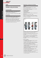
Comfort Functions
Day-Night contactors
This contactor was designed to be used in dual
tariff (Day-Night) applications. The number one
application for this contactor is the control of an
electrical water heater (fig.4).
In general, a day-night contactor is controlled by an
output contact of a dual-tariff meter. On and off
impulses, sent by the energy-supplier over the
powerline-network, are decoded in the meter and
switch the output contact to the on or off state,
switching in its turn the day-night contactor on or off.
0-Auto-1-switch
The additional 0-Auto-1-switch allows the user to
overrule the normal operation of the contactor (fig.5).
For normal operation, this switch is in the Auto-position
and the day-night contactor is operated by the output
contact of the dual-tariff energy meter. In the example
of the electrical water heater, the water will only be
warmed up during off-peak hours (i.e. at night with
minimum price per kWh)
O-position
Putting the lever in the O-position completely
isolates the circuits controlled by the contactor, no
matter what the position of the output contact on
the dual-tariff meter, for example when the service
is not required over a longer period.
1-position
With the lever in this position, the contactor is
forced to its ”on” position. In the example of the
electrical water heater, one would put the switch in
this position after coming back from holidays to
force the heating on if the switch was in the ”O”
position during the holiday. Should, by coincidence,
the user forget to switch the level to the auto-
position again after the forced operation, the device
will return automaticaly to the automatic operation
as soon as the coil is energised (by the contact of
the energy-supplier meter).
Switching capacity
Depending on the type of load, the switching
capacity of a contactor can change drastically.
Indeed, the interrupting capacity of any switch, not
only a contactor, is quite different for DC than for
AC or for pure ohmic loads than for inductive or
capacitive loads. Tables 1 and 2 indicate the
maximum current/power that the different contactor-
families can switch reletive to the type of load.
Typically for lighting applications, table 3 indicates
in detail the number of lamps or transformers each
family of contactors is capable of switching, reletive
to the power per unit. As always, these figures are
per phase and at 230V-50Hz.
T4
fig.4
fig.5
0-Auto-1-switch
Switching of heaters and motors (table 1)
CTX 20
20A
4.0 kW
-
-
9A
1.3kW
-
-
CTX 24
24A
5.3 kW
9.0 kW
16.0 kW
9A
1.3 kW
2.2 kW
4.0 kW
CTX 40
40A
8.7 kW
16.0 kW
26.0 kW
22A
3.7 kW
5.5 kW
11.0 kW
CTX 63
63A
13.3 kW
24.0 kW
40.0 kW
30A
5.0 kW
8.0 kW
15.0 kW
Two current paths connected parallel permit 1.6 x Ie (AC-1)
AC-1/AC-7a Switching of heaters
Rated operational current Ie
Rated operational power
230 V 1 ∼
230 V 3 ∼
400 V 3 ∼
AC-3/AC-7b Switching of motors
Rated operational current Ie
Rated operational power
230 V 1 ∼
230 V 3 ∼
400 V 3 ∼