
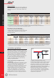
Specifications


T4
T4.54
GE Power Controls
Comfort Functions
Avoid installing an SPD downstream of a
sensitive RCD
An MOV-based SPD always has a leakage current
towards earth. Normally, this leakage current is in
the µA-range and therefore negligible, but for a lot
of SPD’s on the market, (i.e. the multipole
SurgeGuard devices), the optical indicator is a LED
which also leaks current to ground. Unfortunately,
the intensity of the multipole device is several mA’s.
As a result, installing an SPD downstream of a
residual current device (RCD) could lead to nuisance
tripping of the RCD. This doesn’t influence the
correct operation of the SPD, but indeed interrupts
the service continuity.
We advise not to install a multipole SurgeGuard
SPD downstream of an RCD with a sensitivity of
less than 30mA.
Bound wires together
In addition to keeping the lines short, where
possible tightly bind the lives and neutral together
over as much of their length as possible, using
cable ties, adhesive tape, or spiral wrap. This is a
very effective way to cancel out inductance.
Avoid sharp bending and winding-up of
conductors
Besides keeping the interconnecting wires as short
as possible, we also advise not to bend those
interconnecting wires in a sharp way, but instead
apply smooth bendings.
Never coil up interconnecting wires.
Both coiling and sharp bending increase the
inductance of the wire drastically.
Follow rigorously the product specific installation
procedure
As each SurgeGuard device comes with a detailed
instruction sheet, please read and follow these
guidelines step by step during the installation of the
SPD.
Regulations and standards
SurgeGuard SPD’s are all designed according to the
following standards (latest version unless indicated
otherwise):
- IEC 61643-1, IEC1643-1
- EN 61024-1, EN 61000-4-4, EN 61000-4-5
- UL1449-2
- VDE 0110-1, VDE 0185 part 100, VDE 0185-103,
VDE 0675-6 (A1 & A2), VDE 0100-534/A1
- BS 6651 (1992)
- AS 1768 (1991)
- ANSI C62.41
Text for specifiers
- In TT- and TN-S-systems only multipole SPD’s are
used while in IT- and TN-C systems only single-
pole SPD’s are used.
- In IT- and TN-S-systems, one SPD is used
between each live-conductor and PE.
- The single-pole SPD’s are all keyed plug-in devices
while the multipole devices are all mono-block.
- All SPD’s have a terminal capacity of 1x50mm
2
or
2x20mm
2
; the Pozidriv terminals are captive.
- The SPD’s can be interconnected with MCB’s
by means of a pin- or fork-type busbar.
- All SPD’s have an optical fault indicator.
- A complete range is available: Class 1, Class 2
and decoupling inductors.
- Devices with a built-in voltage-free auxiliary
contact for remote indication are available.
- All MOV-based SPD’s must have a built-in thermal
fuse.
- The power-supply voltage is allowed to vary in the
range of 110% Un... 85% Un without damaging
the SPD.