
Specifications


Installation guidelines
Although the installation of an SPD is relatively easy
and can be done very fast, correct installation is vital.
Not just for the obvious reasons of electrical safety
but also because a poor installation technique can
significantly reduce the effectiveness of the SPD.
Below some installation guidelines are summarised
in order to assure the best possible protection
against over-voltage surges you can achieve by
applying SurgerGuard SPD’s.
Install a high quality ground (PE) and avoid
ground-loops
Proper grounding and bonding is important to achieve
a source of equal potential, ensuring that electronic
equipment is not exposed to differing ground
potentials that would introduce ground loop currents.
A high impedance towards ground introduces an
additional voltage drop in series with the residual
voltage of the SPD (fig.15), so the lower this
impedance towards ground, the lower the total
residual voltage across the load to be protected.
Bonding was not a concern in past years because
computers, and all other devices, were
predominantly stand-alone devices and the ground
connection was simply a safety measure for that
single device. However, in recent years we have
begun interconnecting various devices via data and
signal cables. Now, with each device having a
separate ground connection, currents begin to flow
between these various ground connections
increasing the possibility of equipment damage.
Figure 16 overleaf shows correct bonded ground
interconnection between PE, SPD and the
equipment to be protected.
T4
T4.52
GE Power Controls
Comfort Functions
HIGH
MEDIUM
LOW
2.5kV
SG SP 2 20 2
SG SP 2 45 2
SG SP 2 65 2
SG SP 2 20 4
SG SP 2 45 4
SG SP 2 65 4
UN
230V
230V
230V
400V
400V
400V
1kV
SG SP 2 20 2
SG SP 2 45 2
(1)
(1)
(1)
(1)
1.8kV
SG MM 2 20 2
SG MM 2 45 2
SG MM 2 20 4
SG MM 2 45 4
SG MM 2 80 4
Level 3
Level 2
Level 1
Level 3
Level 2
Level 1
Level 3
Level 2
Level 1
MAIN PANEL
45kA
65kA
65kA
(1)
45kA
45kA
45kA
20kA
20kA
20kA
SUBPANEL
-
-
20kA
-
-
20kA
-
-
-
MAIN PANEL
45kA
(1)
65kA
(1)
65kA
(1)
45kA
80kA
65kA
(1)
45kA
45kA
45kA
SUBPANEL
20kA
20kA
45kA
20kA
20kA
45kA
20kA
20kA
20kA
MAIN PANEL
45kA
65kA
65kA
(1)
45kA
65kA
65kA
(1)
20kA
20kA
45kA
SUBPANEL
20kA
20kA
45kA
20kA
20kA
20kA
-
20kA
20kA
(1) Due to high protection needs, the Class 2 SPD needs to be installed together with the Class 1 for the positions marked with "(1)".
(2) If a lightning rod is installed on a building in Your facility or on a building in a radius of 5km around Your facility, or if some high towers,
antennas or trees are in that same radius, we advise to install minimum a 65kA SPD.
(1) If the protection level cannot be reached by using only one SPD, appropriate cascading is necessary. Example: To protect computer equipment in a facility with a high
FER and a level 1 FF&V and with an IT or TN-C earthing system, according to table 5 a 65kA SPD with a U
P=1kV is required but not available. Therefore cascading a
SurgeGuard SP 2 65 2 upfront of a SurgeGuard SP 2 20 2 downstream, with a SurgeGuard C40 in between if required would be the best solution.
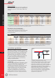
Table 5
FACILITY LEVELS INSTALLATION POINT
FER FF&V Domestic TertiaryIndustrial
fig.15
Step 3: Lookup I
MAX
Based on the Facility Exposure Risk level (FER) and
the Facility Function and Value factor (FF&V), table 5
advises the value of I
MAX
of the SPD or SPD’s to be
installed.
Determination of the SurgeGuard type
The I
MAX-value found above, together with the
operating voltage, the protection voltage and the kind
of earthing system, determines the correct Surge-
Guard type (Table 6).
IMAX/UP
20kA
45kA
65kA
20kA
45kA
65kA
Network
1.8kV
SG SP 2 20 2
SG SP 2 45 2
SG SP 2 65 2
SG SP 2 20 4
(1)
(1)
IT or TN-C single pole SPD
2.5kV
SG MM 2 20 2
SG MM 2 45 2
SG MM 2 20 4
SG MM 2 45 4
SG MM 2 80 4
1kV
SG MM 2 20 2
SG MM 2 45 2
SG MM 2 20 4
SG MM 2 45 4
(1)
TT or TN-S multipole SPD
Table 6