
Specifications


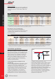


T4
T4.50
GE Power Controls
Comfort Functions
All types are equipped with 50mm
2
terminals 2
with captive Pozidriv screws. The terminal-position
is aligned with the terminal-position of the Elfa+
MCB’s offering the benefit of interconnecting both
devices with a pin- or fork-type busbar.
Easy DIN-rail extraction as is implemented on the
MCB’s and RCD’s is also being used here due to
the same DIN-rail clip used
3 .
All single-pole SPD’s are keyed plug-in-devices
4
and have a mechanical fault indicator, 5 while all
multipole devices are mono-block (not plug-in) and
have an LED fault indicator
6 .
The whole range of class 2 SurgeGuard SPD’s is
available with or without a voltage-free auxiliary
contact for remote indication
7 .
Both the auxiliary contact as well as the fault
indicator reflect the status of the thermal fuse, and
thus indirectly also the status of the MOV (see
explanation below and fig.13).
Once the fault indicator turns red and the auxiliary
contact has switched over, the SurgeGuard should be
replaced as soon as possible since from that moment
on there is no overvoltage protection.
What’s inside
Class 2 SurgeGuard devices all have MOV-
technology inside. The wiring diagram of a single-
phase multipole SurgeGuard is drawn in the figure
below.
Besides the MOV’s, each phase and the earth are
also equipped with a thermal fuse
1 in order to
take the device OFF-line in case the MOV breaks
down and becomes a short-circuit (i.e. after
thermal runaway).
In addition, all devices have an optical fault
photo 1
Phase
Neutral
D3
T1
T2
T3
F1
F2
RV1
RV2
RV3
R3
D1 R1
C1 C2
Q1
C2
DS1
K1
J1
fig.13
5
2
7
7
4
6
2
1
3
indicator 2
and some have a voltage-free contact
for remote indication
3
.
The class 1 SurgeGuard devices are based on
spark-gap technology. As a spark gap can never
turn into a short-circuit, the class 1 devices don’t
have a thermal fuse and as a consequence neither
an auxiliary contact nor an optical status indicator.
Selecting the correct SPD
The correct selection of an SPD is based on 3
factors:
I
MAX
This key parameter is determined based on a risk
analysis (see below) that takes into account:
- the number of lightning days per year (=keraunic
level),
- the geometry of the facility,
- the environment directly in the neighbourhood of
the facility,
- the way in which the power is distributed,
- the value (£) of the equipment to be protected
- etc.
U
P
Determined by the sensitivity of the equipment to be
protected. As a rule of thumb, the figures of table 2
above can be used for this purpose.
Power supplier network
As already explained above, different earthing-
systems require different SPD’s:
- Single-pole for IT and TN-C
- Multipole for TT and TN-S.
Also the voltage and the number of phases of the
power supply have an influence on the selection of
the SPD.
Determination of I
MAX
Step 1: Facility exposure analysis
- The more lightning strikes per year, the higher the
risk of the building being hit:
Figure 14 shows the map of the world with
isokeraunics superimposed on it. (Isokeraunic =
line of same number of lightning days per year).
For each area, a more accurate map should be
available at the Metreologic Institute of the
country.
Locate the area of the facility and read the
keraunic level.
Keraunic level above 80 (High risk) 4
Keraunic level between 30 and 80 (Medium risk) 2
Keraunic level below 30 (Low risk) 1
- The higher the building or the bigger its ground-
surface, the higher the risk of the building being
hit with a lightning-strike:
Multi-story building 4
Single story with roof <10m 2
Single story building 1