
Specifications


T4.38
GE Power Controls
Comfort Functions
Energy (kWh) meter
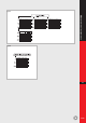
Figures 14 to 18 show the different ways of
connecting the single and three-phase energy
meters. The impulse output can be used to monitor
the amount of consumed energy from distance (i.e.
connection with counter-input-card of PLC).
Like the digital Ammeters, correct set-up of the
current inputs is accomplished by means of dip-
switches located at the front-top of the device
(fig.19 next page).
The impulse output also needs to be correctly set-
up. Figure 20 (next page) shows the setting of the
dip-switches for the use of different current
transformers and for different impulse output
setups.
T4
fig.17
fig.18fig.15
fig.16
fig.14