
Specifications


T4.36
GE Power Controls
Comfort Functions
Voltmeter
In the case of a digital voltmeter, besides the
connection of the circuit of which the voltage needs
to be measured, an independent auxiliary power
supply needs to be connected as is shown in figure 3.
The fact that the measuring circuit is different
from the supply circuit makes this voltmeter
extremely versatile, as it can be used to measure
all voltages within its scale. This also minimises
the measuring error due to the load-influence of
the voltmeter itself.
When using one single-phase voltmeter in a
3-phase system, the different line-to-line or
line-to-neutral voltages can be measured by
using the voltage selector switch (fig.4).
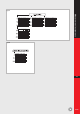
Ammeter
Similar to the previous 3 figures, figures 5 to 7 show
the connection diagrams for the Ammeters.
T4
fig.3
fig.6
fig.7
fig.4
fig.5
fig.2 Connection diagram