
Specifications


T4
T4.17
Impulse switches
Transformer type
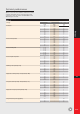
Transformers for low voltage halogen lamps
PLS xx 10 13 (+ PLS C + PLS M)
PLS xx 10 25 (+ PLS C + PLS M)
PLS xx 11 13 (+ PLS C + PLS M)
PLS xx 11 25 (+ PLS C + PLS M)
PLS xx 20 13 (+ PLS C + PLS M)
PLS xx 20 25 (+ PLS C + PLS M)
PLS xx 22 13 (+ PLS C + PLS M)
PLS xx 22 25 (+ PLS C + PLS M)
PLS xx 40 13 (+ PLS C + PLS M)
PLS xx 40 25 (+ PLS C + PLS M)
PLS S xx 20 13
PLS S xx 20 25
PLS C xx xx 14
PLS C xx xx 26
TR B 15
15VA
12V
3
0
3
0
3
0
1
0
1
0
3
0
26
0
TR B 8 S
8VA
12V
1
0
1
0
1
0
0
0
0
0
1
0
13
0
TR S 15
15VA
24V
0
3
0
3
0
3
0
1
0
1
0
3
0
37
TR S 26
25VA
24V
0
5
0
5
0
5
0
2
0
2
0
5
0
61
TR S 41
40VA
24V
0
8
0
8
0
8
0
3
0
3
0
8
0
98
TR S 64
63VA
24V
0
12
0
12
0
12
0
5
0
5
0
12
0
154
Text for specifiers
- Depending on the application, electro-mechanic
or electronic impulse can be used.
- 1 and 2 pole impulse switches have a width of
1 module, 3 and 4 pole devices have a width of 2
modules.
- The position of each contact is individually
shown.
- Manual operation is possible at all time by means
of a toggle.
- The captive Pozidriv terminals have a capacity of
2x(0.5 to 2.5)mm
2
for the control circuit and
1 to 10mm
2
for the load circuit.
- The terminals do guarantee a solid and reliable
connection.
- Permanent use of the control circuit is allowed for
the 1- and 2-pole devices, although in this case a
spacer-module must be added every second
impulse switch.
- The devices are DIN-rail mountable.
- The protection degree of the impulse switch is
IP20.
- The impulse switch is equipped with a transparent
circuit indicator.
- Add-on modules for distant reporting (auxiliary
contact) and centralised command are available
as well as all-in-one central command impulse
switches and multi-circuit impulse switches.
Switching of transformers (table 3)
P (W)
20
50
75
100
150
200
300
10 A
20
8
5
4
2
2
1
25A
60
24
16
12
8
6
4
Permitted number of transformer
TR B 5
5VA
12V
1
0
1
0
1
0
0
0
0
0
1
0
8
0
TR B 10
10VA
12V
2
0
2
0
2
0
0
0
0
0
2
0
17
0
TR S 15
15VA
12V
3
0
3
0
3
0
1
0
1
0
3
0
26
0
TR S 25
25VA
12V
5
0
5
0
5
0
2
0
2
0
5
0
43
0
TR S 40
40VA
12V
8
0
8
0
8
0
3
0
3
0
8
0
69
0
TR S 63
63VA
12V
12
0
12
0
12
0
5
0
5
0
12
0
109
0
Number of impulse switches as function of voltage step-down transformer (table 4)
Transformer data
16 A
39
15
10
7
5
3
2