
Specifications


T4
T4.15
Impulse switches
Electronic impulse switches
Here the two stable positions are generated by means
of a bi-stable electronic circuit that operates a build-in
miniature relay. In photo 4 one can see the front view of
this device with the cover closed as well as open.
The main characteristics are printed on the upper
part of the device
1 .
As opposed to the electromechanical impulse
switches, manual operation is not possible.
The position of each contact is visualised by means
of a LED
3 .
The circuit that is operated by this impulse switch
can be indicated behind the circuit indicator
4 i.e.
hall, living, garage, … .
The Pozidriv terminals
5
are clearly marked and are
all captive.
The add-on-centralised command module cannot
be applied to the electronic impulse switches.
Instead, special electronic impulse switches with
this function already built-in, are available. This
reduces cabling time.
General remarks
- When using the centralised command function,
make sure that the same polarity is used for the
local command as for the central command.
Figure 11 shows correct and erroneous
connection of the centralised command module.
- Using impulse switches at low voltage, and
especially when several impulse switches can be
operated simultaneously (i.e. centralised
command), ultimate care should be taken to the
correct dimensioning of the step-down
transformer (see also table 4 on page T4.17).
- When the control voltage is continuously applied,
a spacer module PLS SP should be mounted
between every second and third impulse switch.
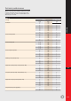
Technical performances
Tables 2 and 3 (next page) show in detail the
maximum number of lamps or transformers that
each contact of an impulse switch can switch at
230V-50Hz for the different families (16, 25 and 32A)
and for different loads.
fig.11b
Central
On
Central
Off
Local
Local
Central
On
Central
Off
Central Local Local Local Local
Central
fig.11a
photo 4
1
4
3
5