ElfaPlus T4.2 T4.5 T4.10 T4.13 T4.18 T4.21 T4.23 T4.25 T4.29 T4.32 T4.35 T4.
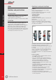
Aster Switches and push-buttons Comfort Functions Introduction The Aster family of devices covers 3 sub-families: - Switches and push-buttons 16 and 32A - Rotary switches 32, 40 and 63A - Mains disconnect switches in 40, 63, 80 and 100A. Function The 16 and 32A switches and push-buttons are mainly used to operate lighting and heating equipment in the commercial sector. For example in warehouses, shops, workshops, hospitals, etc. Rotary switches are mainly used as main switch.
Rotary switches O Important: In case the handle is mounted on the door, the panel can only be opened when the handle is in the OFF-position. The emergency handle can be sealed by means of up to 3 padlocks. fig.1 photo 2 O 2 Switches and push-buttons Features Photo 2 shows the front view of the rotary switches. The main characteristics are printed in the upper part of the device 1 .
Mains disconnect switches Features Photo 4 shows the front view of the mains disconnect switches. The main characteristics are printed in the upper part of the device 1 . These are: - Switching capacity - Operating voltage - Wiring diagram - 6-digit ordering code Related to the switching capacity, versions in 40, 63, 80 and 100A exist. All devices can be used up to 440V. The red handle 2 draws the attention to the fact that this is a mains disconnect switch.
Contax Contactors Function fig.1 Start-stop of a mono-phase lamp-load As long as the control circuit (coil) is energised, the NO-contacts are closed and the NC-contacts are opened. From the moment the control circuit is deenergised again, the contacts return to their rest position. NO-contacts are opened and NC-contacts are closed. Features and benefits In photo 1, the front views of the 1, 2 and 3 module contactors are shown. The main characteristics of the device are printed in the upper part 1 .
Day-Night contactors Comfort Functions This contactor was designed to be used in dual tariff (Day-Night) applications. The number one application for this contactor is the control of an electrical water heater (fig.4). fig.4 0-Auto-1-switch The additional 0-Auto-1-switch allows the user to overrule the normal operation of the contactor (fig.5). For normal operation, this switch is in the Auto-position and the day-night contactor is operated by the output contact of the dual-tariff energy meter.
Switching of DC (table 2) Type DC-1 (L/R ≤ 1ms) DC-3 (L/R ≤ 2ms) 1 current path 24.0 A 21.0 A 17.0 A 7.0 A 0.9 A 2 current paths series 24.0 A 24.0 A 24.0 A 16.0 A 4.5 A 3 current paths series 24, 0 A 24.0 A 24.0 A 24.0 A 13.0 A 1 current path 16.0 A 8.0 A 4.0 A 1.6 A 0.2 A 2 current paths series 24.0 A 18.0 A 14.0 A 6.5 A 1.0 A 3 current paths series 24.0 A 24.0 A 24.0 A 16.0 A 4.0 A CTX 40 24 VDC 48 VDC 60 VDC 110 VDC 220 VDC 40.0 A 23.0 A 18.0 A 8.0 A 1.0 A 40.0 A 40.0 A 32.0 A 17.0 A 5.
Table 3 (continued) Lamp type Comfort Functions Metal-halogen lamps eg. HQI, HPI Low pressure sodium vapor lamps High pressure sodium vapor lamps Lamp data Watt In (A) uncompensated 35 0.53 70 1 150 1.8 250 3 400 3.5 1000 9.5 2000 16.5 2000/400V 10.5 3500/400V 18 parallel compensation 35 0.25 70 0.45 150 0.75 250 1.5 400 2.5 1000 5.8 2000 11.5 2000/400V 6.6 3500/400V 11.6 uncompensated 35 1.5 55 1.5 90 2.4 135 3.5 150 3.3 180 3.3 200 2.3 parallel compensated 35 0.31 55 0.42 90 0.63 135 0.
Endurance fig.8A Endurance curve (Operations vs. switching-off current) AC-1/400 V 3- for CTX 24, 40, 63 AC-1/230 V 1- for CTX 20 General remarks Contactors In general, the guaranteed number of operations at nominal load in AC1 is called the electrical service life. The Contax and Contax DN contactors all have an electrical service life of 150000 operations (Note: 1 cycle = NO → NC → NO = 2 operations).
Contax R Relays Comfort Functions Function Relays are electromechanically controlled switches used to control single or multi-phase low to medium power loads while the control itself can be (very) low power. Also, relays are often used as interfaces to obtain galvanic separation. Typical applications are given in figure 1 and 2. fig.1 Start-stop of lamp-load with relay Features Photo 1 shows the front view of a 1 and 2 module relay. The main characteristics are printed in the upper part of the device 1 .
Technical performances Tables 1 and 2 show in detail the maximum number of lamps and transformers respectively that each contact of a relay can switch at 230V-50Hz for the different types of loads. Table 1 Lamp type Lamp data Perm. number of lamps In (A) 0.065 0.108 0.174 0.260 0.330 0.430 0.650 0.870 1.300 2.170 16A 153 92 57 38 30 23 15 11 7 4 18 20 30 36 40 58 65 0.370 0.370 0.365 0.430 0.430 0.670 0.670 14 14 14 12 12 8 8 2 x 18 2 x 20 2 x 30 2 x 36 2 x 40 2 x 58 2 x 65 0.370 0.370 0.365 0.
Table 2 Transformer type Comfort Functions Transformers for low voltage halogen lamps Transformer data P (W) 20 50 75 100 150 200 300 Text for specifiers - 1 and 2 pole relays have a width of 1 module, 3 and 4 pole devices have a width of 2 modules. - Permanent use of the control circuit is allowed although in this case a spacer-module must be added every second relay. - The maximum switching frequency is equal to 1000/h at nominal load. - The position of each contact is individually visualised.
Pulsar S fig.4 Impulse switches Function Impulse switches Impulse switches are electromechanical or electronically controlled switches used to control single or multi-phase medium-power loads while the control itself can be (very) low power. The device switches between 2 stable positions, each time a (brief) impulse energises its control circuit. Typical applications are given in figure 1 to 4. fig.1 Electromechanical impulse switches fig.
Comfort Functions photo 2 fig.8 Remote indication of the contact position can be accomplished by means of the add-on auxiliary contact module PLS 0411 (photo 2). The auxiliary contact can only be mounted on the left side of the device. Independent of coil voltage or number of contacts, always the same add-on module for centralised command PLS C can be used (photo 3). The centralised command module can only be mounted on the right side of the device.
Electronic impulse switches Here the two stable positions are generated by means of a bi-stable electronic circuit that operates a build-in miniature relay. In photo 4 one can see the front view of this device with the cover closed as well as open. O O O photo 4 O 1 O O General remarks - When using the centralised command function, make sure that the same polarity is used for the local command as for the central command.
Switching of lamp load (table 2) Lamp type Comfort Functions Permitted number of lamps P (W) 15 25 40 60 75 100 150 200 300 500 In (A) 0.065 0.108 0.174 0.260 0.330 0.430 0.650 0.870 1.300 2.170 10 A 66 40 25 16 13 10 6 5 3 2 16 A 153 92 57 38 30 23 15 11 7 4 25A 240 144 90 60 48 36 24 18 12 7 18 20 30 36 40 58 65 0.370 0.370 0.365 0.430 0.430 0.670 0.670 11 11 11 9 9 6 6 14 14 14 12 12 8 8 22 22 22 19 19 12 12 2x18 2x20 2x30 2x36 2x40 2x58 2x65 0.370 0.370 0.365 0.430 0.430 0.670 0.
Switching of transformers (table 3) Transformer type Transformer data Permitted number of transformer 10 A 20 8 5 4 2 2 1 16 A 39 15 10 7 5 3 2 25A 60 24 16 12 8 6 4 Number of impulse switches as function of voltage step-down transformer (table 4) PLS xx 10 13 (+ PLS C + PLS M) PLS xx 10 25 (+ PLS C + PLS M) PLS xx 11 13 (+ PLS C + PLS M) PLS xx 11 25 (+ PLS C + PLS M) PLS xx 20 13 (+ PLS C + PLS M) PLS xx 20 25 (+ PLS C + PLS M) PLS xx 22 13 (+ PLS C + PLS M) PLS xx 22 25 (+ PLS C + PLS M) PLS xx 40
Pulsar TS Staircase switches Comfort Functions Function and range A staircase light switch is a special purpose delayoff timer. In addition to a delay-off timer, the staircase switch will allow a certain amount of (limited) current to pass through the coil without energisation. This current usually comes from illuminated push-buttons, used to help people in a dark staircase find these push-buttons.
O this case we cannot use one common wire for the push-buttons and for the lamps as in the above wiring diagram. For this setup, 4-wire wiring as shown in figure 9 is required. Also in this case the PE-conductor is not shown. fig.9 Staircase swithces Also in this case, the function of the staircase time switch or the circuit that it operates can be indicated behind the circuit indicator 2 .
Comfort Functions Figure 11 shows in detail the different voltagewaveforms as function of time: - V1 = supply voltage waveform passing the contact of the staircase switch, - V2 = supply voltage waveform passing the contact of the dim-add-on module, - V3 = resulting voltage waveform applied to the load. When applying an additional wire as shown in figure 13, the current drawn by the bulbs of the illuminated push-buttons is sunk through this wire instead of through the coil of the staircase switch.
Pulsar T Timing relays Function Use of incoming impulses to give predictable output-impulses. Timing relays Operating functions and applications Figures 1 to 6 show the different timing functions together with the applications. fig.1 Delay On (PLT ON) Avoid drive-way light-up in case the movement detector "accidently" detects someone passing by. fig.4 Positive edge single shot (PLT PS) Opening of automatic door.
Programming Except for the multifunction timing relay, all devices have two dials to set the delay (see photo 1). The upper one 1 is the preset of a time i.e. from 0.1 sec to 4 h. The lower one 2 is the multiplier of this time. The product of both gives the actual time delay. Comfort Functions O O photo 1 O 3 O O 1 2 Examples - Requested delay time is 7 minutes: put upper switch on 1 min and lower switch on 7. - Requested delay time is 40 minutes: put upper switch on 5 min and lower switch on 8.
Classic photo 2 Introduction O O 4 The Classic family of electromechanical timers is used to switch loads on and off, according to a preprogrammed switch-plan, as a function of time. This range of electromechanical timers covers 1and 2-channel devices, net- or quartz-synchronised with a daily or/and weekly program. O OO 1 2 O 5 6 O 7 Operation A motor drives a dial with switches. When put in their ‘ON’ state, these switches mechanically operate a contact.
Comfort Functions Terminology Program per channel Examples - 1x24x2 is a daily timer (1x24); minimum duration between 2 subsequent switchings (=shortest switching time) is 30 minutes (x2). - 7x24:3 is a weekly timer (7x24); minimum duration between 2 subsequent switchings is 3 hours (:3). - 1x24x4 & 7x24:12 is timer with a combined daily and weekly program (1x24 and 7x24); minimum duration between 2 subsequent switchings is 15 minutes for the daily dial (x4) and 2 hours for the weekly dial (:12).
Galax photo 2 OO O OO O O O 5 3 6 Introduction The Galax family of digital timers is used to switch loads on and off, according to a pre-programmed switch-plan, as a function of time. This range of microprocessor based timers goes from a simple 1-channel, quartz synchronised, daily programmable device with 12 programming steps, mainly used for domestic purposes, up to a 4channel DCF-77 synchronised yearly timer with 400 programming steps for high-feature-demanding industry.
Comfort Functions Galax specifications (table 1) Program per channel Number of modules Number of channels Number of programming steps Block programming Manual override per channel Summer-Winter time change Cycle / Impulse function Random function Clear function Reset function Calendar / Holiday function DCF-77 PC-programmable Running reserve Daily GLX Q 21 D 12 1X24X60 2 1 12 no yes yes no no yes yes no no no 3 yr GLX Q 11 W 42 7X24X60 1 1 42 yes yes yes no yes no yes no/yes no no 150h GLX Q 21 W 20 7X
fig.1 CHANNEL x ACTIVE PULSE/CYCLE DEFINITION IMPULSE Calendar/Holiday function The yearly programmable timers have the possibility to repeat a switching program during a certain period. i.e. programmed heating and lighting of a workshop: - Lighting from 7:30 till 15:45, all year around except for the summer- (July 15 till August 15) and Christmas-holidays (i.e.
Comfort Functions Programming Text for specifiers Programming Tools Besides programming the GLX Q 6 digital timers manually, it is also possible use the Galax Programming Tool. This tool consists of - a Windows-95 (and up) compatible software with very easy to use and straightforward GUI - a handheld programming device - an RS232 serial cable to interconnect the programming device with the PC.
Galax LSS fig.2 Light sensitive switches Channel 1 450 LUX Function and range Light intensity > 450 Lux O Both channel 1 and 2 are in their de-energised A O As long as the light intensity is above the switch-on threshold value, the output relay remains deenergised and the output contact is open (see 1 in fig.1).
Comfort Functions Multilevel/multichannel light sensitive operation with 1 photocell Based on the external light intensity, the light intensity of a (large) room can be adjusted in order to keep the overall light intensity in the room unchanged (see fig.4 and table 1). Remark When using only 1 photocell with several (max 10) 2-channel light sensitive switches, only on 1 light sensitive switch terminal 10 needs to be connected to terminal 12 while on all others, terminal 10 is to be left open (see also fig.
Setting up a twilight switch for correct operation Remarks 1. If the LED is still off and you are at full scale, then the intensity of the ambient light is over 500 Lux at that time. A filter should be applied to the photocell and the procedure should be carried out again. 2. If while selecting the threshold, the no-response delay is other than 0, please bear in mind that the output-relay won’t switch immediately. 3.
Series T Transformers Comfort Functions Function and range Transformers are mainly used for 2 reasons: - To galvanically separate one circuit from the other and / or - To step down the energy supplier network voltage in order to supply low voltage circuits. Two main different subfamilies exist in the complete Series T range of transformers: - Bell transformers and - Safety transformers.
One combined vs. two separate secondary windings or voltages In a transformer with one combined secondary winding for 2 voltages, obviously the cross section of the wire is the same for the whole secondary winding. The different output voltages are derived by connecting at different places of the one secondary winding (see fig.3). fig.3 Let’s assume the power of the transformer in figure 3 being 15VA and two secondary voltages being 12 and 8V.
Comfort Functions General remarks Text for specifiers - DO NOT put secondary windings of transformers in parallel in order to increase the output power, as the slightest difference in output voltage will result in a huge current circulating in both secondary windings (see fig.6). - All transformers have the CEBEC - IMQ - VDE approval marks. - All transformers have their nominal output power available on all different output voltages. - All transformers are protected against shortcircuits.
Series MT Measurement Instruments Function and range The digital range consists of: - voltmeters - Ammeters - frequency meters - kWh meters - energy meters - net analysers On top of this, several accessories complete the range: - a complete range of current transformers, - a complete range of corresponding scale-plates, - selector switches for switching a single phase measurement instrument between the different phases of a 3-phase energy distribution system, - a very user friendly Windows-95 (and up) soft
Voltmeter fig.2 Connection diagram Ammeter Similar to the previous 3 figures, figures 5 to 7 show the connection diagrams for the Ammeters. Comfort Functions fig.5 In the case of a digital voltmeter, besides the connection of the circuit of which the voltage needs to be measured, an independent auxiliary power supply needs to be connected as is shown in figure 3.
The scaleplates of the analogue Ammeters can be easily interchanged as is illustrated in photo 1. fig.11 Using a digital Ammeter in combination with a current transformer, requires the correct set-up of the Ammeter. The multiplying factor is set by means of dip-switches as is shown in figure 8. fig.8 Wattmeter Measurement instruments photo 1 The single- and three-phase Wattmeters are connected as shown in figures 12 and 13. fig.
Comfort Functions Energy (kWh) meter T4 T4.38 fig.16 Figures 14 to 18 show the different ways of connecting the single and three-phase energy meters. The impulse output can be used to monitor the amount of consumed energy from distance (i.e. connection with counter-input-card of PLC). Like the digital Ammeters, correct set-up of the current inputs is accomplished by means of dipswitches located at the front-top of the device (fig.19 next page). The impulse output also needs to be correctly setup.
fig.19 Measurement instruments fig.20 T4 T4.
Comfort Functions Net analysers (Multi Meters) The series MT DN 1 and MT DN 3 are electronic instruments especially developed for measuring and controlling several electrical parameters such as voltage, current, power, energy, harmonic distortion in a single or three phase network. All the measured values can be viewed in real time on the analyser display or transmitted to a remote display (PC/PLC) through a serial interface RS 485 (except the harmonic waves).
By pressing ENTER, the third subpage shows the values of the active/reactive energy of the 3rd tariff meter. +kWh +kVARh -kWh -kVARh (3) (3) (3) (3) 00000000.00 00000000.00 00000000.00 00000000.00 CONFIG Meter Inputs Password (4) (4) (4) (4) 00000000.00 00000000.00 00000000.00 00000000.00 By pressing ENTER, the fifth subpage shows the actual peak values (IPM) and previous (IPL), integrated in 15 min., of the active/reactive energy +kWh +kVARh +kWh +kVAR IPM IPM IPL IPL 00000000.00 00000000.
By choosing ‘Inputs’ and pressing UP, the following screen appears: inp.1 inp.2 ener IP tarifs: 2(4) Comfort Functions >inp.1 >inp.2 >ener IP 000 /imp 000 /imp 15 min >exit by pressing UP or DOWN, you change the ‘weight’ of the impulses on the digital input n° 1 by pressing UP or DOWN, you change the ‘weight’ of the impulses on the digital input n° 2 by pressing DOWN, you can modify the integration time of the totals by pressing UP, you see the synchronisation screen of the input n° 1 inp.1 inp.
Typical setups for serial communication fig.24 Net analysers fig.25 fig.26 T4 T4.
Background SurgeGuard Disturbances Table 1 summarises the different disturbances causing different problems while propagating in an electrical energy-distribution system. Besides devices used to suppress overvoltage transients, typically characterised by a very big magnitude (1000’s of volts) and very short duration (microseconds), devices for noise filtration (low voltage, low energy, random) are also offered.
Protection levels (table 2) UP=2.5kV Terminology Before going into more detail in technology matters, this chapter clarifies most of the SPD-related terminology. IMAX Is the maximum current the SPD can carry (deviate to ground). According to the standard, an SPD should be able to carry this current at least once. Class The Class of the SPD defines the amount of energy the device is able to deviate towards the protective ground.
becomes a short-circuit (i.e. after thermal runaway). In addition, all devices have an optical faultindicator and some have a voltage-free contact for distant reporting. This contact reflects the status of the thermal fuse, and thus indirectly also the status of the MOV. Once the indicator turns red or the contact has switched over, the SurgeGuard should be replaced as soon as possible. The class 1 SurgeGuard devices are based on spark-gap technology.
Different earthing systems require different SPD’s As you can easily see, the clamping voltage between live and neutral is UP1 + UP2, which is roughly twice the clamping voltage of a varistor and not once as may be expected. This results in a very poor degree of protection. Therefore, in this case an additional varistor between each live conductor and the neutral is necessary to guarantee full protection (see fig.3). fig.
Comfort Functions IT and TN-C earthing systems require single-pole SPD’s As can be seen in figure 5, the main difference between a TT- and an IT-earthing system is the high impedance Z through which the generator or the secondary of the step-down-transformer is grounded in an IT-system. Therefore, the low-impedant current-path towards the PE of the energy-supplier which exits in a TTsystem, no longer exists in an IT-system, and for this reason will never conduct current.
fig.9 green: residual voltage red: 8/20 current impulse fig.10 fig.11 300 mA EP30 C16/C20 F2 SG 80kA EP30 C16/C20 300 mA F3 SG 20kA 30 mA SG 45kA or 20kA installation should the surge arrester fail. It also allows the disconnection of the SPD for service or maintenance. To be effective, the circuit breaker or fuse directly upstream of the SPD should be capable of cutting the theoretical short-circuit current at the place where the SPD is installed.
O O O O indicator 2 and some have a voltage-free contact for remote indication 3 . The class 1 SurgeGuard devices are based on spark-gap technology. As a spark gap can never turn into a short-circuit, the class 1 devices don’t have a thermal fuse and as a consequence neither an auxiliary contact nor an optical status indicator.
Ground surface more than 4500 m2 Ground surface from 2000 to 4500 m2 Ground surface less than 2000 m2 4 2 1 - The higher the density of the buildings in the area, the lower the risk of your building being hit with a lightning strike: 4 2 1 - An overhead power supply has a higher risk of being hit by a lightning strike than an underground supply: Overhead direct service drop Overhead to facility then underground Underground service from utility substation Metropolitan service grid 4 3 2 1 - Also, the fu
Step 3: Lookup IMAX Based on the Facility Exposure Risk level (FER) and the Facility Function and Value factor (FF&V), table 5 advises the value of IMAX of the SPD or SPD’s to be installed.
fig.16 Use Kelvin connections Wherever possible, ordinary parallel connections as shown in figure 17 should be avoided and Kelvin connections as shown in figure 18 should be applied. This way of connecting virtually reduces the additional voltage-drop in the connecting wires to zero, obtaining the best UP possible. fig.
Comfort Functions Avoid installing an SPD downstream of a sensitive RCD An MOV-based SPD always has a leakage current towards earth. Normally, this leakage current is in the µA-range and therefore negligible, but for a lot of SPD’s on the market, (i.e. the multipole SurgeGuard devices), the optical indicator is a LED which also leaks current to ground. Unfortunately, the intensity of the multipole device is several mA’s.