
User`s manual


63
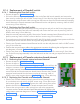
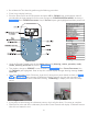
8.17.2 Fixing the new Input power cord
• Take the new power cord which comes along with grommet assembly and separate the grommet as-
sembly into three parts as shown in Figure 124 then take out the grommet nut and keep aside.
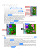
• Insert the power cord cable along with the cable grommet holding part & cable grommet flexible part
from the bottom side of the base unit as shown in the Figure 125 .
Note: Do not tighten the cable grommet flexible part till the procedure tell to do so.
• Fix the locking nut of cable grommet (flat portion first) into the cable from inner side of the base unit
as shown in the Figure 125 .
• Pull the power cord inside the base unit upto required length and tighten the cable grommet nut hold-
ing the grommet flexible part at bottom side of the base unit as shown in Figure 126 .
Figure 124
Figure 125 Figure 126
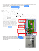
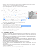
• Route the power cord cable through the hole provided in the base unit clamp as shown in Figure 122 .
Connect the “Line, Neutral and earthing wires (Ring terminals) of the power cord on the terminal block
using cross recessed screw driver as shown in Figure 122 . Fix the clamp used for holding the power
cord at the bottom side of the terminal block as shown in Figure 122 .
• Execute the steps in "8.2.2.5 Base unit Covers Fixing:"
• Perform "5.6 Ground Connection Check:".
• Perform "5.12 Power On Check:".
8.18 Replacing the Console extension cables
• Console wxtension cable set contain two cables in the package:
a)Console communication cable connected between power board and console extension board.
b) Console board cable connected between console board and Console extension board.
Replace the particular defective cable by following the procedure given below.
• Execute the steps in "8.2.1.1 Power Off:".
• Execute the steps in "8.2.1.3 Base Unit Cover removal:"
If console communication cable fails:
• Disconnect one end of the defective cable from the J4 connector on the power board by accessing
from the bottom side of the base unit and other end from Connector "PB" on the console extension
board.
• Connect one end of the new console communication cable to the connector-PB of the console exten-
sion board and route the cable through the hole on the base unit rear cover and connect the other
end of the cable to the J4 connector of the power board from the bottom side of the base unit.