
User`s manual


62
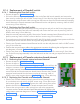
• Connect the “Live(Blue) and Neutral(Black) wires(Ring terminals) of switch” to the terminal block fixed
on the power board clamp using phillips screw driver as shown in Figure 119 .
• Execute the Steps as in "5.9 Base unit cover fixing:".
• Execute the Steps as in “5.12 Power On Check:”.
8.17 Replacing the input power cord
8.17.1 Removing the old input power cord
• Execute the Steps as in “8.2.1.1 Power Off:”.
• Execute the steps as in “8.2.1.3 Base Unit Cover removal:”.
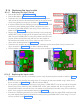
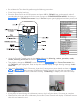
• Disconnect the “Live, Neutral and GND wires(Ring terminals) of power cord connected to the termi-
nal block using screw driver as shown in Figure 122 and remove the clamp which is used to hold the
power cord at bottom to the terminal block by removing 2 M3X6 HSHC screws using 2.5 mm allen key
as shown in Figure 122 .
M3x6 HSHC
screw on top of
power board
Earthing point
on power
board plate
Terminal block for
connection be-
tween power cord
and input Switch
2 M3x8 HSHC
screws with jam
nuts
Cable
clamp
Figure 122
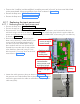
• Remove the power board clamp from the
base unit by removing 1 M3X6 HSHC Screw
on top side of the power board using 2.5
mm allen key and 2 M3X8 HSHC screws,
plain washers and Jam nuts (screws will be
inserted from rear side and nut with washer
to be fixed from front side) using 2.5 mm
allen key and 5.5 mm nut driver at the loca-
tions shown in Figure 122 .
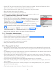
• Loosen the cable grommet clamp as shown in Figure 123 . Loosen
the grommet nut inside the Base Unit as shown in Figure 123 and
remove the grommet & the cable out of the Base Unit (through the
cable entry hole).
Figure 123