
User`s manual


58
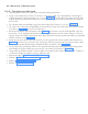
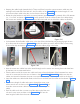
8.10.3 Fixing the Scissor-Arm End caps
• For fixing back the scissor-arm end caps first, align the rubber part of scissor-arm as shown in Figure
110 .
• Take end cap of one side (half) and fix to the scissor-arm such that the rubber part should be aligned
in the slot as shown in Figure 111 .
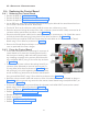
• Now take another half of end cap and insert such that the holes provided in both the caps are aligned
properly and insert the other side of rubber part into the slot provided in the second half of the end
cap as shown in Figure 112 .
Figure 110 Figure 111
Figure 112
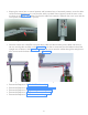
• Fix the bottom caps of the straight-arm with M3x6 self tapping CSK head screws using screw driver.
• Execute the Steps as in “5.12 Power On Check:”.
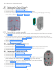
8.11 Replacing the exposure switch
• Execute the Steps in "8.2.1.1 Power Off:".
• Disconnect the defective exposure switch by disconnecting the cable from the
bottom side of the base unit as shown in Figure 113 .
• Take the new exposure switch and connect its cable at the bottom side of the base
unit as shown in Figure 113 .
• Perform “5.12 Power On Check:”.
Figure 113
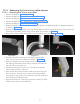
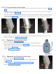
8.12 Replacing the Scissor-arm end caps
• Execute the Steps in "8.2.1.1 Power Off:".
• Remove the defective end caps. Do not remove the rubber part shown
in Figure 114 .
• Execute the steps in " 8.10.3 Fixing the Scissor-Arm End caps".
• Perform "5.12 Power On Check:".
Figure 114