
User`s manual


57
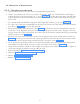
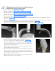
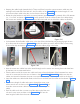
• Keeping the vertical arm in vertical position and horizontal arm in horizontal position, route the cable
inside the horizontal arm such a way that the cable is pushed 20mm (approx) inside the outer cover
as shown in the Figure 106. Make sure that the cables are inserted in between the outer cover and the
inner plastic sheet (not visible in picture).
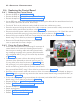
Figure 106 Figure 107
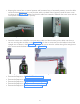
• Insert the scissor-arm cable(First communication cable and then Inverter power cable) into the scis-
sor arm swivel guide as shown in the Figure 107 such that it comes out from the bottom hole of the
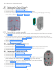
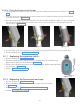
straight arm as shown in the Figure 108 . Use guide wire to route the cables through the straight arm
till it comes inside the base unit as shown in Figure 109 .
Figure 108 Figure 109
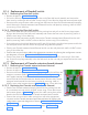
• Execute the Steps as in “8.2.2.2 HV Tank Assembly:”.
• Execute the Steps as in "8.2.2.3 Scissor-arm cable connection:".
• Execute the Steps as in “8.2.2.4 Tube Head Covers Fixing:”.
• Execute the Steps as in "5.6 Ground Connection Check:".
• Execute the Steps as in "5.9 Base unit cover fixing:".