
User`s manual


56
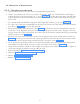
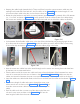
• Keeping the cable length (towards the L-Clamp end) fixed, route the communication cable near the
rotating bush (inside the outer hole of L Arm) as shown in the Figure 99 (Leave extra length of 1 turn
of communication cable within the circular area as shown in Figure 99 ).
• Rotate the tube head arm and hold it at central position (approximate 270° position) of the full rotation
(i.e., 0° to 540° as shown in Figure 100 ). At this position route the cables (scissor arm cables along
with scissor arm earthing wire) inside the slot of the tube head arm such that the cables are flexible.
Figure 99 Figure 100
Figure 101
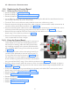
• In the position fix the flexible cable cover in the slot of the tube head arm by sliding through the arm
till it comes out the as shown in Figure 101 and fix the cable cup with 2 M3x25 HSHC screws using
2.5mm allen key as shown in Figure 101 and fix the rubber plugs in the holes.
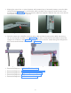
• Now the scissor arm cables has to be routed through out the scissor arm starting from tube head arm
till the base unit as mentioned below.
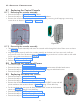
• Take the other end of the scissor arm cable and route it from the bottom of the horizontal arm outer
cover till it comes out from the arm as shown in the Figure 102 & Figure 103 . Make sure that the
cables are inserted in between the outer cover and the internal plastic sheet(not visible in the figure).
• Insert the cables into cable holder fixed on the fulcrum and take out from other end as shown in Figure
103 .
Figure 102 Figure 103
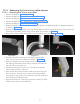
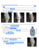
Figure 104
Figure 105
• Pull the extra length of cable and insert it through the outer cover
of the vertical arm as shown in the Figure 104 & Figure 105 (First
route the communication cable and then route the Inverter power
cable).
• Push the cable such that it comes out of the other end of the verti-
cal arm’s outer cover as shown in the Figure 104 . Pull out the
extra length of cable from the outer cover.