
User`s manual


55
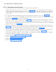
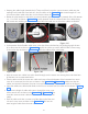
8.10.2 Assembly Steps for Scissor-Arm Cable
• Hold the end of the Cable harness (Figure 94 ) and insert the communication wire (cable with connec-
tor) from the hole of swivel guide (Figure 95 ) till it comes out of the tube head arm as shown in Figure
96 .
• Now insert the Inverter power cable (cable without connector) in the same way till it comes out of the
tube head arm as shown in the Figure 95 and Figure 96 .
• Pull both the cables together such that the communication cable measures 27.5" (approx) & Inverter
power cable measures 21.2"(approx) from the opening of the tube head arm end as shown in the Fig-
ure 96 .
Figure 94 Figure 95 Figure 96
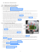
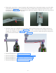
Figure 97
• Insert the communication cable inside the hole provided on the wire slot side of the tube head arm as
shown in the Figure 97 & then the Inverter power cable along with the scissor arm earthing wire as
shown in the Figure 97 such that the wire comes out of the L arm circular bush.
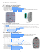
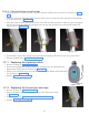
• Insert the cables (scissor arm cables along with scissor arm earthing wire) from the hole of the rotating
bush such that it comes out of the L-Clamp as shown in the Figure 98 . Ensure that the other end of
the Scissor arm earthing wire is already connected firmly to the L arm (near the rotating bush).
Figure 98
• Pull the scissor arm cables such that the length of the communication cable measures 9.84"(approx)
from the connector to the surface of the L-Clamp and length of the Inverter power cable measures
6"(approx) from the connector to the surface of the L-Clamp as shown in the Figure 98 using measur-
ing tape.
Imp Note: - Keeping the L-Clamp as reference, route the cables such that the communication cable is
towards the dual hole end & the Inverter power cable along with the scissor arm grounding wire is towards
the single hole end end of the L-Clamp.