
User`s manual


53
8. Service Procedure
8.7 Replacing the Control Console
8.7.1 Removing the console assembly
• Execute the Steps in “8.2.1.1 Power Off:” above.
• Execute the steps in “8.2.1.3 Base Unit Cover removal:” above.
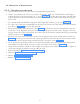
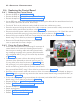
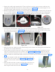
• Remove the console assembly from base unit front cover by removing 4 self tapping screws using
screw driver as shown in Figure 87 and Figure 88 .
Figure 88
Figure 87
8.7.2 Removing the console assembly
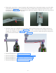
• Take the new console assembly and route the console cable through the hole of front cover as shown
in Figure 88 .
• Align the gasket properly and fix the console assembly to the base unit front cover with 4 self tap-
ping screws at the screw locations shown in Figure 87 using screw driver. Lock the cable on the cable
mount using cable tie as shown in Figure 87 .
• Perform "5.9 Base unit cover fixing:".
• Perform “5.12 Power On Check:”.
8.9 Replacing the Base unit Covers
• Execute the Steps in "8.2.1.1 Power Off:".
• Execute the steps in "8.2.1.3 Base Unit Cover removal:".
• Execute the steps in "8.4.1 Removing the Power Board".
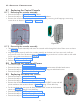
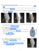
• Remove the old base unit rear cover by removing 6 M3x6 HSHC screws and M3
plane washers at the locations shown in Figure 89 using 2.5mm allen key.
• Fix the new base unit rear cover by fixing 6 M3x6 HSHC screws at the locations
shown in Figure 89 using 2.5 mm allen key.
• Execute the steps in "8.4.2 Fixing the power board".
• Execute the steps in "8.2.2.5 Base unit Covers Fixing:".
• Execute the steps in "5.12 Power On Check:".
Figure 89
8.8 Replacing the Tube Head Covers
• Execute the Steps in "8.2.1.1 Power Off:".
• Execute the steps in "8.2.1.2 Tube Head Cover Removal:" and remove old tube head covers.
• Execute the steps in "8.2.2.4 Tube Head Covers Fixing:" using new tube head covers.
• Execute the steps in "5.12 Power On Check:".