
User`s manual


52
8. Service Procedure
8.6 Replacing the Control Board
8.6.1 Removing the Control Board
• Execute the Steps in “8.2.1.1 Power Off:”.
• Execute the Steps in “8.2.1.2 Tube Head Cover Removal:".
• Execute the steps in "8.2.1.3 Base Unit Cover removal:".
• Use an ESD wrist strap while connecting and disconnecting the cables of the control board and con-
nect its GND connection to the HV Tank Clamp.
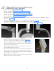
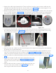
• On the HV Tank cut the cable ties used to hold the scissor arm cables using cutter.
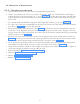
• Press the connector locking tab and pull the cable connector (communication cable) connected to J4
connector of the control board as shown in the Figure 86 .
• Disconnect the INV power cable from the sealing board 3 pin connector-pins 1 & 3 (hold the connec-
tor firmly by hand while removing) using Jewel screw driver as shown in the Figure 86 .
• Remove the screws used for GND wire connections for both cables at all 4 corners of the Control
board using 2.5mm Allen key as shown in Figure 86 .
• Remove the Control Board and keep it in an Antistatic
cover or protected from Static charges.
8.6.2 Fixing the Control Board
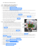
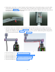
• Fix the new Control Board by connecting J3 connector of
control board to J3 connector of sealing board and fix
the scissor-arm earthing cable and sealing board earth-
ing wires(Ring terminals) to the nearest control board fix-
ing screw(M3x6 HSHC) using 2.5mm allen key as shown
in Figure 86 .
• Connect the INV power cable to the sealing board 3 pin
connector (Non polarised pin terminal wires to pins1 &
3) using Jewel screw driver as shown in Figure 86 (Hold
the connector f irmly while tightening the terminal screws)
and fix its GND ring terminal to the nearest control board
Figure 86
fixing screw(M3x4-HSHC) using 2.5mm allen key as shown in the Figure 86 .
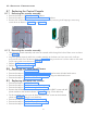
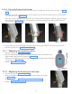
• Route the communication cable and connect it to the J4 connector of the control board as shown in
Figure 86 and fix its ground ring terminal to the nearest control board fixing screw(M3x4 HSHC) as
shown in the Figure 86 .
• Fix the tube head ground ring terminal(near the colimator) with M3x4 HSHC screws on the control
board using 2.5mm allen key as shown in Figure 86 .
• Execute the Steps in "8.2.2.4 Tube Head Covers Fixing:”.
• Perform “5.6 Ground Connection Check:”.
• Execute the steps in "5.9 Base unit cover fixing:".
• Switch on the power.
• Perform “9.2 Tube Head Re-Calibration”.
• Perform “5.12 Power On Check:”.