
User`s manual


51
8. Service Procedure
8.5.2 Fixing the new tube head
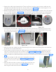
• Take the HV-Tank and fix it to the clamp using the following sequence:-
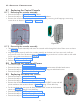
• Using 2.5mm allen key & 5.5mm nut driver fix 3 Hex. Soc. head cap screws(M3X16) with M3 plain
washers & M3 nuts (at the locations 9 to 11 as in Figure 85 ) such that the screw along with M3 plain
washer should be inserted from bottom and nut along with M3 plain washer should be on the top of
the HV Tank.
• Fix 5 button head screws(M3X6) using 2mm allen key(at the locations 1 to 5 as in Figure 85 ).
• Fix 3 Hex. Soc. Head cap screws(M3X6) on the top of the clamp near Tube head arm at the locations
(6 to 8 as in Figure 85 ) using 2.5 mm Allen key.
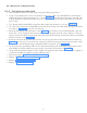
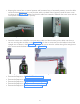
• Route the INV power cable as shown in the Figure 84 and connect it to the sealing board 3 pin con-
nector (Pin 1 & 3). Hold the connector firmly while tightening the terminal screws. Using a 2.5mm al-
len key connect the GND ring terminal of the INV cable to the nearest control board fixing screw(M3x4
HSHC) as shown in the Figure 84 .
• Route the communication cable and connect it to the J4 connector of the control board as shown in
Figure 84 and using a 2.5mm allen key connect the GND ring terminal of the communication cable
to the nearest control board fixing screw(M3x4 HSHC) as shown in the Figure 84 .
• Fix the scissor-arm grounding cable on the control board along with sealing board grounding cable
with M3X6 Hex. Socket Head cap screw using 2.5mm Allen key as shown in Figure 84 .
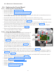
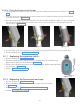
• Using cable ties(100mm length or 50mm length is enough) ties the cables on the HV Tank. Tighten &
cut the extra length of cable ties using a cable tie cutter.
• Execute the steps “8.2.2.4 Tube Head Covers Fixing:”.
• Perform “5.6 Ground Connection Check:”.
• Perform "5.9 Base unit cover fixing:".
• Perform “5.12 Power On Check:”.