
User`s manual

49
8. Service Procedure
8.4.2 Fixing the power board
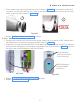
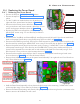
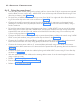
• Take the new power board (along with its plate) and fix it (ensure that J3 & J4 connectors are inserted
into the Base Unit rear cover) with 1 M3X6 HSHC screw on the top side of Power Board using 2.5mm
allen key as shown in the Figure 83 .
• Fix the 4 Nos. of M3X6 Hex socket head cap screw 2 on left & 2 on right side of the Power Board us-
ing 2.5mm allen key to the rear cover as shown in Figure 83 .
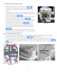
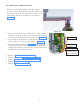
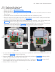
• Connect the wires(Pin terminals) coming from the switch to the J5 connector on the power board
(holding the connector firmly by hand) as shown in Figure 82 (Live=Blue & Neutral=Black) using a
Jewel screwdriver.
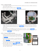
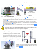
• Fix back the power board clamp to the base unit by fixing 1 M3X6 HSHC Screw on top of the power
board using 2.5mm allen key and 2 M3X8 HSHC screws, plain washers and Jam nuts (screws to be
inserted from rear side and nut with washer to be fixed from front side) using 2.5mm allen key and
5.5mm nut driver shown in Figure 81 .
• Connect the GND wire to the GND terminal on power board plate just below the switch using 1M3X6
HSHC screw (with washers) using 2.5mm allen key as shown in the Figure 81 .
• Connect the “Live(Blue) and Neutral(Black) wires(Ring terminals) coming from switch to the terminal
block fixed on the base unit clamp using phillips screw driver as shown in Figure 81 .
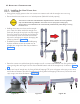
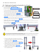
• Connect the Inverter power cable to J1 connector(Non-polarised) using screw driver and connect
communication cable connector to J2 connector on the power board by pressing the lock as shown in
Figure 80 .
• Connect the GND wires of both the cables by fixing with M3x6 HSHC screws using 2.5mm allen key
as shown in Figure 80 .
• Use new cable ties to fix the cables on the existing cable mounts & cut the extra length of cable ties
using a cable tie cutter.
• Perform “5.6 Ground Connection Check:”.
• Execute the steps in "5.9 Base unit cover fixing:".
• Perform “5.12 Power On Check:”.