
User`s manual

47
8. Service Procedure
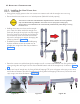
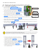
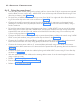
• Route the scissor-arm cables through the straight-
arm till it comes inside the base unit (Use guide wire
for routing and guide with finger from the slots avail-
able bottom side of the straight arm) as shown in
Figure 78 .
Figure 78
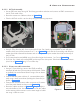
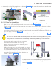
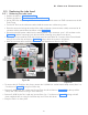
• Connect the Inverter power cable from J1 connector(Non-
polarised) using screw driver and communication cable to
J2 connector on the power board as shown in Figure 79 .
• Fix the GND wires of both the cables by fixing M3x6 HSHC
screws using 2.5mm allen key as shown in Figure 79 .
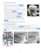
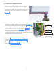
• Route the cables as shown in Figure 79 along the right
inner side of the Base Unit. Use new Cable ties to fix the
cables on the existing cable mounts & cut the extra length
of cable ties using a cable tie cutter.
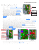
Inverter
cable(J1)
Communica-
tion cable(J2)
Ground point
Cable ties
Figure 79
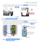
• Perform “5.6 Ground Connection Check:”.
• Execute the steps in "5.9 Base unit cover fixing:".
• Perform "5.10 Scissor-Arm Operation Checking".
• Perform "5.11 Other Checks:".
• Perform “5.12 Power On Check:”.