
User`s manual

46
8. Service Procedure
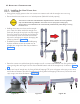
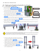
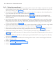
• Remove the circlip of the straight arm as shown in Figure 73 and remove the straight arm from the base
unit as shown in Figure 74 .
8.3.2 Fixing the Straight-Arm
• Take the new straight arm ad fix it on the base unit as shown in Figure 74 and lock the straight arm to
base unit with circlip using 90 deg angled circlip pliers as shown in Figure 73 .
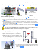
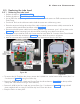
• Check and confirm the level of the straight-arm using spirit level by rotating to all directions as shown
in Figure 75 .
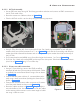
• Remove the bottom caps of the new straight-arm by removing M3x6 self tapping CSK screws using
screw driver and remove the end cap of the straight-arm by removing M3x6 self tapping CSK screw us-
ing screw driver as shown in Figure 69 .
• Remove M8x25 positive lock screw of the new straight arm using 6 mm Allen key as shown in Figure
70 .
Figure 74
Figure 73
The scissor arm with tube head attached is shipped tied close. Remove the securing cable tie only when
directed during installation. The scissor arm can spring open causing injury.
Always make sure to hold both arms of the assembly simultaneously while lifting or moving the scissor
arm.
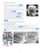
Figure 75
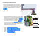
Apply grease
as necessary.
• Using gloves, apply grease to the new scissor-arm
insertion rod and the straight arm inner ring.
• Ensure that the new scissor-arm is in locked position
(folded & locked properly).
• Holding the scissor-arm close to the straight arm, insert
the cables inside the straight arm (free end) through the
top hole into the straight arm till it comes out at the free
end of straight arm and slowly insert the Scissor-Arm
assembly into the straight arm without damaging the
cables as shown in Figure 76 .
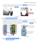
Figure 76
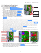
• Fix M8x25 positive lock screw and M8 spring & plane washers
to lock the scissor arm to straight arm using 6mm allen key as
shown in Figure 77 .
Figure 77