
User`s manual

45
8. Service Procedure
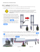
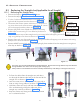
8.3 Replacing the Straight-Arm(Applicable for all length)
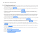
Inverter
cable(J1)
Communica-
tion cable(J2)
Ground point
Cable ties
Figure 68
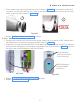
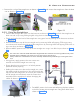
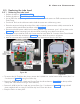
• Pull out the cables from the straight-arm and take it
out through the bottom side hole at the free end of the
straight arm as shown in Figure 71 .
• Lock the scissor arm in folded position by tying with a
knot or using a long cable tie as shown in Figure 72 .
• Hold the scissor-arm firmly with both hands and slowly
lift it simultaneously pulling the cables out of the
straight arm carefully as shown in Figure 72 .
• Keep the Scissor-arm along with tube head separate
on a cushioned surface.
Figure 72
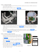
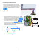
• Remove 2 bottom caps of the straight arm by removing M3x6 self tapping screws (2 screws for each
cap) using phillips screw driver as shown in Figure 69 .
• Remove front end cap of straight arm by removing one M3x6 self tapping screw at bottom side using
phillips screw driver as shown in Figure 69 .
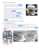
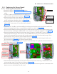
• Remove M8x25 positive lock screw and M8 spring & plane washers from the straight arm using 6mm
allen key as shown in Figure 70 .
Figure 70
Figure 69
Figure 71
The scissor arm with tube head attached is shipped tied close. Remove the securing cable tie only when directed
during installation. The scissor arm can spring open causing injury.
Always make sure to hold both arms of the assembly simultaneously while lifting or moving the scissor arm.
8.3.1 Removing the Straight-Arm
• Execute the Steps in "8.2.1.1 Power Off:" above.
• Execute the steps "8.2.1.3 Base Unit Cover removal:".
• Cut the 2 cable ties inside the base unit located on the
right side of the power board as shown in Figure 68 .
• Disconnect the Inverter power cable from J1 connector us-
ing screw driver and communication cable from J2 connec-
tor on the power board as shown in Figure 68 .
• Remove the GND wires of both the cables by removing
M3x6 HSHC screws using 2.5 mm Allen key as shown in
Figure 68 .