
User`s manual

44
8 Service Procedure
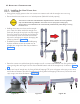
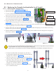
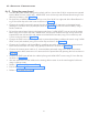
• Fix the rubber fixing ring on the positioning cone as shown in Figure 65 (1) and slide the rubber dial
ring and fix it in the slot so that the arrow mark on ring should be alligned to centre line of tube head
covers on the front side as shown in Figure 65 (2).
• Perform “5.6 Ground Connection Check:” as above..
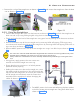
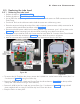
8.2.2.5 Base unit Covers Fixing:
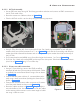
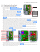
• Take the base unit front cover and connect the console cable to the J5 connector on the “Console exten-
sion PCB-Internal” located top of the power board as shown in Figure 66 .
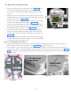
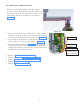
• Fix the base unit cover with two M3x6 HSHC screws and M3 plane washers on top using 2.5mm allen key
and one M3x25 self tapping screw at bottom using phillips screw driver as shown in Figure 67 . Put back
the rubber caps on top and bottom at the screw locations.
Figure 66
M3X25 Self tapping
screw(Use Phillips
screw driver)
Figure 67
M3x6 Hex socket
head cap screws(Use
2.5mm allen key)
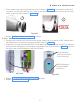
• Perform “5.10 Scissor-Arm Operation Checking” as above.
• Perform “5.12 Power On Check:” as above.
Figure 65
1
2