
User`s manual

43
8 Service Procedure
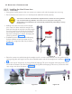
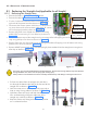
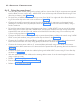
Figure 62
• Route the INV power cable as shown in the Figure 62 and
connect it to the sealing board 3 pin connector (Pin 1 &
3). Hold the connector firmly while tightening the terminal
screws.
• Using a 2.5mm allen key connect the GND ring terminal of
the INV cable to the nearest control board fixing screw(M3x4
HSHC) as shown in the Figure 62 .
• Route the communication cable and connect it to the J4 con-
nector of the control board as shown in Figure 62 .
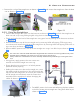
• Using a 2.5mm allen key connect the GND ring terminal of
the communication cable to the nearest control board fixing
screw(M3x4 HSHC) as shown in the Figure 62 .
• Fix the scissor-arm grounding cable on the control board
along with sealing board grounding cable with M3X6 Hex.
Socket Head cap screw using 2.5mm Allen key as shown in
Figure 62 .
• Using cable ties(100mm length or 50mm length is enough)
ties the cables on the HV Tank. Tighten & cut the extra length
of cable ties using a cable tie cutter.
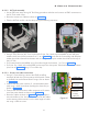
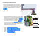
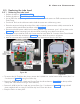
8.2.2.4 Tube Head Covers Fixing:
• Take the tube head top cover and fix it using 4 (M3X16 self tapping pan head) screws with 4 (M3)
plane washers at the locations shown in the Figure 63 using a screw driver.
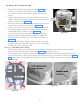
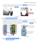
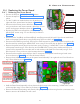
• Fix the bottom cover to the tube head assembly using 2 M3X6 hex socket button head screws using 2
mm allen key and fix 2 M3x16 self tapping pan head screws using screw driver as shown in the Figure
64 . Ensure there is no gap between the covers. Put back the 4 rubber plugs at the screw locations on
the Tube Head.
Figure 63
Figure 64