
User`s manual


40
8. Service Procedure
8.2.1.6 Final Steps before Removal
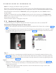
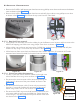
• Remove 2 bottom caps of the straight arm by removing M3x6 self tapping screws (2 screws for each cap)
using phillips screw driver as shown in Figure 51 .
• Remove front end cap of straight arm by removing one M3x6 self tapping screw at bottom side using
phillips screw driver as shown in Figure 51 .
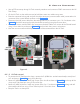
• Remove M8x25 positive lock screw and M8 spring & plane washers from the straight arm using 6mm al-
len key as shown in Figure 52 .
Figure 51
Figure 52
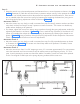
• Lock the scissor arm in folded position by tying with a knot or using a long cable tie.
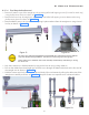
• Pull out the cables from the straight-arm and take it out through the bottom side hole at the free end of
the straight arm as shown in Figure 53 .
• Hold the scissor-arm firmly with both hands and slowly lift it simultaneously pulling the cables out of the
straight arm carefully as shown in Figure 54 . Keep the Scissor-arm separate on a cushioned surface.
Figure 53 Figure 54
The scissor arm with tube head attached is shipped tied close. Remove the securing cable tie
only when directed during installation. The scissor arm can spring open causing injury.
Always make sure to hold both arms of the assembly simultaneously while lifting or moving
the scissor arm.