
User`s manual


39
8. Service Procedure
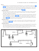
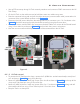
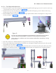
8.2.1.5 HV Tank removal
• To remove the HV Tank from the clamp, remove the 5 (M3X6 Hex. socket button head) screws (from 1
to 5 as shown in Figure 50 ) using 2mm allen key.
• Remove 3 (M3X6 Hex. Soc. Head cap) Screws (From 6 to 8 as shown in Figure 50 ) on the top of the
clamp near Tube head arm using 2.5mm allen key.
• Remove 3 (M3X14 Hex Soc. head cap) screws (from 9 to 11 as shown in Figure 50 ) along with M3
plain washers & M3 nut using 2.5mm allen key and 5.5mm Nut driver.
• Keep the Tank in a clean place.
Figure 49
Figure 50
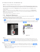
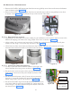
• Use an ESD wrist strap during HV Tank removal procedure and connect its GND connection to the HV
Tank Clamp.
• On the HV Tank cut the cable ties used to hold the scissor arm cables using cutter.
• Press the connector locking tab and pull the cable connector (communication cable) connected to J4
connector of the control board as shown in the Figure 49 .
• Disconnect the INV power cable from the sealing board 3 pin connector -pins 1 & 3 as shown in the
Figure 49 (hold the connector firmly by hand while removing) using Jewel screw driver.
• Remove the screws used for GND wire connections for both cables at 3 corners of the Control board
using 2.5mm allen key as shown in Figure 49 and put back the screws in its location.
• Now the communication and INV power cables are disconnected from the HV Tank.