
User`s manual


38
8 Service Procedure
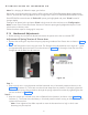
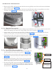
• Remove the 2 M3X16 self tapping pan head screws using phillips screw driver and remove the bottom
cover as shown in the Figure 43 .
• Remove the 4 M3X16 self tapping pan head screws with M3 plain washers using phillips screw driver
as shown in the Figure 44 and remove the top cover from the Tube Head.
Figure 44
Figure 43
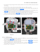
8.2.1.3 Base Unit Cover removal:
• On the Base Unit assembly, remove the rubber plug at the Bottom screw location and then remove the
M3X25 self tapping pan head screw using phillips screw driver as shown in Figure 45 .
• Lift the rubber cap on the top and remove the 2 M3X6 Hex. socket Head cap screws with M3 plain
washers on top using 2.5 mm allen key as shown in the Figure 46 .
• Lift the base unit front cover slowly and disconnect the Console cable from J5 connector of Console
extension board-internal located on the power board as shown in Figure 47 .
Figure 45
Figure 46
Figure 47
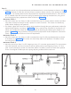
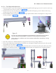
8.2.1.4 Scissor-arm cables disconnecting
• Cut the 2 cable ties used to hold the cables on the right inner
side of the Base Unit using cutter as shown in Figure 48 .
• Disconnect the communication cable connector (Pressing the
lock) from J2 connector of the power board as shown in the
Figure 48 .
• Disconnect the INV power cable (2 wires with pin terminals )
from the J1 connector (holding the connector) of the power
board using Jewel screw dr iver as shown in Figure 48 .
• Disconnect the GND ring terminals of both INV cable and com-
munication cable by removing the M3X6 Hex. Socket head cap
screw using 2.5 mm allen key from the power board at the loca-
tion shown in the Figure 48 .
Inverter
cable(J1)
Communica-
tion cable(J2)
Ground point
Cable ties
Figure 48