
User`s manual


37
8 Service Procedure
8.1 Replacement Guide
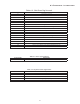
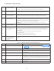
Table 8-1: Replacement Parts list
Part Failed Part to be replaced
If the Scissor Arm or parts of Scissor arm including L- Arm fails/is damaged Scissor Arm
Anything fails inside the Tank Tube Head
If the control Board inside the Tube Head fails Control Board
If the Tube Head Cover is damaged Tube Head Covers
If the Power Board fails Power Board
If the Base Unit Cover is damaged Base Unit Cover
If exposure Switch with Cable is damaged Exposure switch with cable
If remote Keypad Console fails Remote keypad console
If door bell Switch fails DC Door bell Switch
If the Scissor Arm cables fails/damaged Scissor Arm cable harness
If the Console Board/ Key Pad/cable/cover fails Entire Console assembly
If the Plastic Caps for Scissor Arm is damaged Plastic Caps for Scissor Arm
If the Straight-Arm fails/is damaged Straight-Arm
If input switch fails Input Switch
If Console extension board-Internal fails Console extension board-Internal
If console extension cables fails Console extension cable
8 Service Procedure
8.2 Replacing the Scissor-Arm:
8.2.1 Removing the old Scissor-Arm:
8.2.1.1 Power Off:
Before starting this procedure, ensure Power to the Unit is OFF, and Console Display is OFF. During the
disassembly procedure collect & keep all removed hardware and small parts in a separate clean container
as it is required for reassembly.
8.2.1.2 Tube Head Cover Removal:
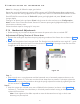
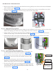
• Remove the “extension cone” from the tube head ( if used).
• Remove the “rubber fixing ring” on the tube head as shown in the Figure 40 .
• Push the “rubber dial ring” out of the slot as shown in the Figure 41 .
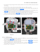
• On the bottom side of the Tube head remove the rubber plugs at 4 locations where the screws are fixed
on the Tube Head and remove the 2 M3X6 button head screws as shown in Figure 42 using 2 mm al-
len Key.
Figure 41
Figure 40
Figure 42