
User`s manual


36
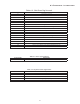
7 Trouble Shooting
Table 7-3: TROUBLE SHOOTING CHART (MECHANICAL)
OBSERVED PROBLEM RECOMMENDED ACTION
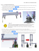
1. Scissor Arm is Drifting from its released
position / does not stay in set position
Adjust the spring tension as described in Section "5.14 Mechanical
Adjustments". If still the drift problem exists then replace the Scissor
arm.
2. Scissor Arm Movement is Tight Replace the Scissor Arm.
3. Noise during Scissor arm movement Remove the rectangular caps of the Scissor Arm at both ends and
apply grease to the springs. If still problem persists then replace the
scissor Arm.
4. Straight-Arm Movement is tight Remove the Straight-Arm and put back after applying grease to all
rotating parts. If still problem persists then replace the defective part.
5. Tube Head movement is loose Remove the cap on the Tube Head L- Arm and check the screw
tightening. You can try to slightly tighten the screw in case they are
loose. Later put back the cap. If the problem still exists then replace
the Scissor Arm.
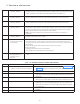
6. Plastic or Rubber Parts damaged Replace the damaged parts as per the FRU (Field Replacement
Units) list.
7. Oil leaking from the Tube Head Replace the Tube Head.
8. Error state with display
indicating CN008
kV Regulation Fault: Recycle the power. Retry to give the exposure. If the problem
persists, check the continuity of the INV-power cable & replace (try with external spare
cable), if problem persists then replace the Power board in the Base unit.
9. Error state with display
indicating CN009
Filament Open Fault: Recycle the power. Retry to give the exposure, If the problem
persists, calibrate the tube head. If the problem still persists, replace tube head.
10. Error state with display
indicating CN010
Filament Limit Fault: Recycle the power. Retry to give the exposure. If the problem
persists, calibrate the tube head. If the problem still persists, replace tube head.
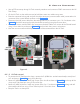
11. Error state with display
indicating CN011
CAN Fault: Recycle the power. Clean the contacts of the Console connector Spiral
chord. Retry to give exposure. If the problem persists, replace the console. If problem
persists, then check communication Cable continuity (try with external spare cable)
and if still not resolved at the end replace Control Board.
Note: Once the Control board is replaced the Tube head has to undergo re-
calibration.
12. Error state with display
indicating KB001
Ensure that none of the console keys depressed accidentally. Recycle the Power. If the
problem persists replace the console.
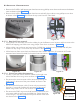
13. The unit does not
power on when mains
is switched on.
Remove the Base Unit Top cover. Check if neon pilot lamp is ON in the power board.
If not, there may be a loose contact at the wall socket end or the wall outlet is not
receiving power. Check local electrical circuit for trips. If neon lamp is ON then check
the following.
Ensure that the spiral cable connection to the base Unit is proper.
Recycle the power.
If problem persists then replace the Console.
If the problem still persists replace the power Board.
14. No x-ray image
even though the unit
indicates normal
exposure
Ensure that there is no Error in the Console. If OK then check the Image receptor
used.