
User`s manual

29
5 Installation of intraskan dc
5.9 Baseunitcoverxing:
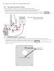
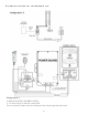
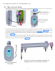
• Take the base unit front cover and connect the console cable to the J5 connector on the “Console exten-
sion PCB-Internal” located on the power board as shown in Figure 33 .
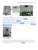
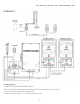
• Fix the base unit cover with two M3x6 HSHC screws and M3 plane washers on top using 2.5mm allen key
and one M3x25 self tapping screw at bottom using phillips screw driver as shown in Figure 34 . Put back
the rubber caps on top and bottom at the screw locations as shown in Figure 34 .
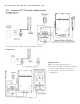
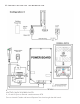
• Connect the exposure switch cable to the J3 connector located at the bottom side of the base unit as
shown in Figure 35 .
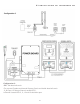
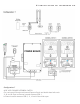
• Fix the end cap of straight arm by fixing M3x6 self tapping CSK screw at bottom side using screw driver
and fix the two bottom caps of the straight arm by fixing M3x6 self tapping CSK screws (2 screws for
each cap) using screw driver as shown in Figure 36 .
Figure 33
M3X25 Self tapping
screw(Use Phillips
screw driver)
Figure 34
M3x6 Hex socket
head cap screws(Use
2.5mm allen key)
Figure 35: Fix exposure
switch cable
Figure 36: Fix end cap and bottom caps(M3x6 self
tapping Counter sunk screws )Use screw driver.