
User`s manual

22
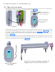
5 Installation of Intraskan dc
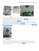
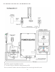
Figure 32: Wire routing hole &
2 mounting holes
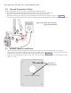
Figure 30-: 4 M3x6Hex socket head cap
screws
Figure 31: Console cable
• Take the remote keypad console assembly. Pull out the console from the slot and remove 4 ( M3x6 HSHC)
screws with M3 plane washers using 2.5 mm allen key as shown in Figure 30 .
• Lift the cover along with console assembly and disconnect the console cable from the J8 connector of the
board and keep the parts aside as shown in Figure 31 .
• Take the base plate of remote keypad console and route the remote console communication cable
through the hole provided on the plate and fix the remote console plate on the stud with 2 M6x30 lag
bolts using 8 mm box spanner at the locations shown in Figure 32 .
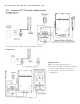
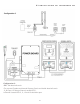
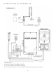
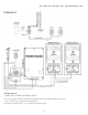
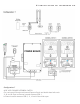
• Connect the remote console communication cable as per the connections shown below in "5.8 Intraskan
DC Console configurations:".
• Follow the same steps for fixing the Doorbell switch assembly as above if door bell switch is used.
• Connect the external console cable to J8 connector and close the cover of the remote console by fixing
4(M3x6 HSHC) screws using 2.5 mm allen key as shown in Figure 30 . Fix back the remote keypad con-
sole in the slot of the cover.