
User`s manual

16
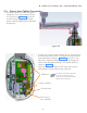
5 Installation of Intraskan DC
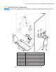
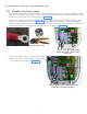
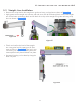
• Fix the base unit rear cover along with power board assembly to the base unit plate with six M3x6
HSHC screws using 2.5mm allen key as shown in Figure 16 . Fix the ground wire coming from ter-
minal block to the grounding location with M3x10 HSHC screw and M3 plane washer using 2.5mm
allen key as shown in Figure 16 .
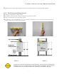
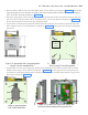
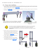
Figure 13: Mark and drill 4 mounting holes
using 5/16-inch wood drill bit.
Figure 16: Fix base unit rear cover along with
powerboardassemblyandxgroundwire.
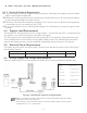
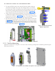
• Remove M3x10 HSHC screw from the plate using 2.5mm allen key as shown in Figure 14 . Locate the
2x4 wood studs to mount the base unit plate and mark template holes and drill 5/16" holes to depth of
3.93" at the four locations as shown in Figure 13 .
• Route the input power cable coming from wall through the hole and fix the optional plate on the wall
with four M10x100 lag screws and M10 washers using 17mm box spanner as shown in Figure 14 .
Ensure that the plate is level on the top using spirit level.
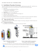
• Fix the base unit plate on the optional plate fixed on the wall with five M10x22 Hex head bolts with
M10 washers using 17mm box spanner as shown in Figure 15 . Ensure the level of plate and tighten
the screws.
Figure 15: Fix base unit
plate on optional plate
with 5 Hex head bolts.
Figure 14: Fix optional plate with 4 lag
screws using 17mm box spanner
M3x10
HSHC
screw