
User`s manual

15
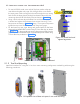
5 Installation of Intraskan DC
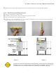
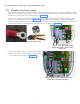
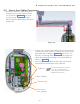
Figure 11: Fix base unit rear cover along with power board.
• Fix one M10X100 wood screw with M10 plane washer at the top
most hole and tighten only upto 3/4 th length of the screw. Route
the input power cable coming from the wall through the wire routing
hole and fix the base plate by sliding from bottom side and fix the
remaining three M10X100 wood screws as shown in Figure 11 .
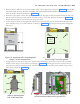
• Using a level indicator adjust the Base Unit such that its top surface
is leveled and tighten all the bottom three screws first using 17mm
box spanner as shown in Figure 10 . Using 17mm open end spanner
tighten the top screw. Reconfirm the level using level gauge.
• Fix the base unit rear cover along with power board to the base
plate with six M3X6 HSHC screws using 2.5mm allen key as shown
in Figure 11 . Fix the ground wire coming from terminal block to the
ground location with M3x6 HSHC screw and M3 plane washer using
2.5mm allen key as shown in Figure 11 .
Figure 10: Check level and
tighten lag screws.
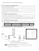
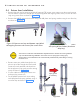
5.1.2 Two Stud Mounting
Install the Intraskan DC using the 16-inch on center mounting configuration method by performing the
following procedures.
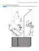
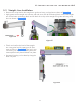
Figure 12: Exploded view of base unit parts in two stud mounting.