
User`s manual

12
4 Pre-Installation Requirements
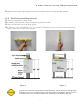
4.3.3 Electrical Outlets & Requirements
The mains outlet should have a good Ground connection. Grounding of the system must be checked
before connecting the Intraskan DC.
Additional wiring required for the site must done by a qualified electrician. All wiring should conform
to requirements provided by the User manual.
The mains outlet should be capable of supplying 16A (110V) of current. It shall have fuse protection
or provided with a circuit breaker of 16A (110V).
It is recommended to have an ELCB (Earth Leakage Circuit Breaker) for protection against earth
leakage.
Line Voltage 110 VAC +/- 10% Exposure Current 8 Amp
Standby Current 0.25 Amp Max. Main Fuse Rating 10 Amp
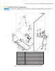
4.4 Support Load Requirements
The Intraskan DC is designed to mount on a single wood 4 x 4 wood stud and two 2 x 4 wood studs that
are spaced 16" on center and drywall or equivalent wall support.
The wall support and mounting hardware for the Intraskan DC must withstand 150 pounds shear load,
and a withdrawal force at each of the mounting bolts of 800 pounds. The wall fabrication and attach-
ments to the building structure must be capable of withstanding a load moment of 1100 pounds.
Note -1
Maximum
Length
Minimum Size
0-50 feet 14 gauge minimum
50-100 feet 12 gauge minimum
100-150 feet 10 gauge minimum
150-250 feet 8 gauge minimum
250-400 feet 6 gauge minimum
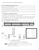
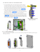
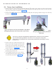
Figure 6. Intraskan DC external wiring Schematic
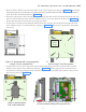
When using Remote console configurations recommended cable length (for 8P8C,
6P4C and 3 wire) is 35' maximum.
No crossover in any of the RJ45 and RJ14 connector cables used for remote console
configuration(i.e,.1 to 1 connections).
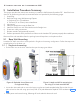
4.5 Electrical Power Requirements
The system requires a three-wire power supply. The three-wires provide two power lines (L) Line and (N)
Neutral and a Ground.
4.6 Wiring Length and Gauge Requirements
Maximum length of wire and minimum gauge wire (AWG) from the power panel box to the Base Unit.