This page is left blank Intentionally.
Table of Contents Table of contents 1 Introduction................................................................................................................................. 6 1.1 About Intraskan DC................................................................................................................... 6 1.2 Scope of this Manual................................................................................................................. 6 1.3 Symbols in this Manual........................
Table of Contents 8.2 Replacing the Scissor-Arm:........................................................................................................37 8.2.1 Removing the old Scissor-Arm:.................................................................................................37 8.2.1.1 Power Off:...........................................................................................................................37 8.2.1.2 Tube Head Cover Removal:..............................................
Table of Contents 8.16.1 Removing the Input Switch.....................................................................................................61 8.16.2 Replacing the Input switch......................................................................................................61 8.17 Replacing the input power cord...............................................................................................62 8.17.1 Removing the old input power cord...............................................
Introduction 1 Introduction 1.1 About Intraskan DC The Intraskan DC High Frequency Intraoral X-ray has been engineered and manufactured to provide many years of reliable service. The system houses two microprocessors, one for control/supervisory functions and another to provide the user/machine interface. The technology incorporates feedback circuits to ensure accuracy and reproducibility of X-ray output for dental diagnostic radiography.
Safety and Precautions 2 Safety and Precautions: 2.1 Geneal Safety Tips Installation of the Intraskan DC must be done only by an authorized service engineer. Consult the factory or dealer as necessary. Make sure that the Intraskan DC is assembled and installed in compliance with all applicable laws and recommendations concerning electrical safety. The unit contains and generates high voltages.
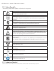
2 Safety and Precautions 2.2 Safety Symbols The following safety related symbols are found on the equipment. Caution Symbol This symbol indicates the user to be cautious and refer to the user manual for safe operating instructions. Protective Earth Ground Mains Earth Ground is required for continued protection against shock hazards. Type of Insulation Class 1, Type B Insulation. Protection against electric shock (UL60601-1:2003). Requires protective Earth Connection.
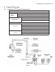
3 Product Overview 3 Product Overview 3.1 Intraskan DC System Components Table 3.1.
4. Pre-Installation Requirements 4 Pre-Installation Requirements 4.1 Tools and Consumable Material Table 4-1 provides a consolidated list of the tools and consumable material which are typically required for executing the installation and service procedures provided by this manual. Table 4-1. Useful Tools and Consumable Material L- type allen Wrench Set including 2 mm, Hand-held Power Drill 1/2 inch Drive Socket Wrench with 8 mm 5/16" wood drill bit. 90 degree Circlip pliers.
4 Pre-Installation Requirements Make sure the location allows sufficient space for movement of the arms in the extended condition. 4.3.2 Site Environment Requirements The unit is designed for indoor usage. It should not be subjected to direct sunlight for expanded duration. Mount it away from sources of liquid ingress. If The X-ray unit is stored below 10° C , time must be allowed for X-ray unit to reach room temperature before connecting it to the mains voltage.
4 Pre-Installation Requirements 4.3.3 Electrical Outlets & Requirements The mains outlet should have a good Ground connection. Grounding of the system must be checked before connecting the Intraskan DC. Additional wiring required for the site must done by a qualified electrician. All wiring should conform to requirements provided by the User manual. The mains outlet should be capable of supplying 16A (110V) of current. It shall have fuse protection or provided with a circuit breaker of 16A (110V).
4 Pre-Installation Requirements 4.7 Included System Components Figure 7 shows the major components and accessories included with a wall mounted Intraskan DC. Verify that all listed items were received for the unit. If any item is missing, take appropriate action to get the missing parts.
5 Installation of Intraskan DC 5 Installation Procedure Summary This section provides the instructions necessary to install the Wall Mounted Intraskan DC. Install the Intraskan DC by performing the tasks summarized below and provided by the following pages. 1. Unpacking. 2. Base Unit fixing using Wall Mounting Options a. Single stud (4" x 4") Installation. b. Two stud (16" on Center) Mount Installation. 3. Input wiring. 4. Install the Straight Arm onto the Base Unit. 5.
5 Installation of Intraskan DC • Fix one M10X100 wood screw with M10 plane washer at the top most hole and tighten only upto 3/4 th length of the screw. Route the input power cable coming from the wall through the wire routing hole and fix the base plate by sliding from bottom side and fix the remaining three M10X100 wood screws as shown in Figure 11 .
5 Installation of Intraskan DC • Remove M3x10 HSHC screw from the plate using 2.5mm allen key as shown in Figure 14 . Locate the 2x4 wood studs to mount the base unit plate and mark template holes and drill 5/16" holes to depth of 3.93" at the four locations as shown in Figure 13 . • Route the input power cable coming from wall through the hole and fix the optional plate on the wall with four M10x100 lag screws and M10 washers using 17mm box spanner as shown in Figure 14 .
5 Installation of Intraskan dc 5.2 Procedure for Input wiring: • Strip the insulation on each input wire for a length of approximately 5 mm. Using the Paladin Crimping Tool with Dies 2035 or equivalent, Crimp the three dowel studs to the Line, Neutral and Ground wires of the Input power cable from wall as shown in Figure 17 . • Remove the cable clamp (located near the input wiring hole) by removing two (M3x6 HSHC) screws using 2.5 mm allen key as shown in Figure 18 .
5 Installation of intraskan DC 5.3 Straight- Arm Installation: • Remove the circlip fixed to the straight-arm guide rod using circlip pliers as shown in Figure 20 . • Apply grease to the straight arm insertion rod and inner area of the bearing block. Mount the straightarm on the base unit bearing block and fix back the circlip to the straight-arm guide rod using circlip pliers as shown in Figure 21 .
5 Installation of intraskan dc 5.4 Scissor Arm Installation • Remove the end cap by removing M3x6 self tapping CSK screws screw using screw driver and remove the two bottom caps of the straight arm by removing M3x6 self tapping CSK screws (2 screws for each cap) using screw driver as shown in Figure 23 . • Remove the M8x25 positive lock screw along with M8 plane and spring washers using 6 mm allen key as shown in Figure 24 .
5 Installation of Intraskan dc 5.5 Scissor Arm Cables Connection • Route the scissor-arm cables through the straight-arm till it comes inside the base unit as shown in Figure 26 (Use guide wire for routing and guide with finger from the slots available bottom side of the straight arm). Figure 26 • Connect the communication cable to the J2 connector and Inverter power cable to the J1 connector using screw driver (Non-polarised) as shown in Figure 27 . Using a 2.
5 Installation of Intraskan dc 5.6 Ground Connection Check: Using a Multimeter, check the continuity between the following points:• Between Ground point of power board and Tube Head inner Cone metal part, • Between Ground point of power board and Scissor Arm Guide rod and • Between Ground point of power board and Base Unit Wall mounting plate as shown in Figure 28 . • If any of the check fails then check the Ground connections inside Base Unit & Tube Head for Cable fault.
5 Installation of Intraskan dc • • • • Figure 30-: 4 M3x6Hex socket head cap Figure 31: Console cable screws Take the remote keypad console assembly. Pull out the console from the slot and remove 4 ( M3x6 HSHC) screws with M3 plane washers using 2.5 mm allen key as shown in Figure 30 . Lift the cover along with console assembly and disconnect the console cable from the J8 connector of the board and keep the parts aside as shown in Figure 31 .
5 Installation of intraskan dc 5.8 Intraskan DC Console configurations: Configuration-1: Can use Internal Console and Internal Exposure Switch. Configuration-2: 8P8C with single door bell switch. Can use two Consoles with Internal Exposu re Switch and single door bell switch. J3: Open and J1, J2:Short on external console PCB.
5 Installation of intraskan dc Configuration-3: 8P8C with door bell switch. Can use two Consoles with Internal Exposure Switch and double door bell switch. J1,J3 Open, J2 Short on External console PCB-1. In External console PCB-2, J1, J2 and J3 should be open.
5 Installation of intraskan dc Configuration-4: 3 WIRE WITH SINGLE DOORBELL SWITCH. J1, J2 and J3 Open on External console PCB. Can use Internal Console with Internal Exposure Switch and single door bell switch.
5 Installation of intraskan dc Configuration-5: 3 WIRE WITH DOUBLE DOORBELL SWITCH Can use Internal Console with Internal Exposure Switch and double door bell switch. J1,J2 and J3 Open on External console PCB-1. In External console PCB-2, J1, J2 and J3 should be open.
5 Installation of intraskan dc Configuration-6 6P4C WITH SINGLE DOORBELL SWITCH. J1, J2 and J3 Open on External console extension PCB. Can use Internal Console with Internal Exposure Switch and single door bell switch.
5 Installation of intraskan dc Configuration-7 6P4C WITH DOUBLE DOORBELL SWITCH. Can use Internal Console with Internal Exposure Switch and double door bell switch. J1,J2 and J3 Open on External console extension PCB-1. In External console extension PCB-2, J1, J2 and J3 should be open.
5 Installation of intraskan dc 5.9 Base unit cover fixing: • Take the base unit front cover and connect the console cable to the J5 connector on the “Console extension PCB-Internal” located on the power board as shown in Figure 33 . M3x6 Hex socket head cap screws(Use 2.5mm allen key) M3X25 Self tapping screw(Use Phillips screw driver) Figure 33 Figure 34 • Fix the base unit cover with two M3x6 HSHC screws and M3 plane washers on top using 2.
5 Installation of intraskan dc 5.10 Scissor-Arm Operation Checking Move the Scissor arm and ensure there is no drift as per steps given below. • Keep the Vertical Arm in vertical position and horizontal arm in horizontal position. • Move the horizontal arm down (folding movement) in small jerk free incremental steps of approximately 10 degrees. • At each step as above, leave the scissor arm and ensure that there is no drift movement. Continue till the horizontal arm reaches vertical position.
5 Installation of intraskan dc Note: For changing kV follow the steps given below: Restart the unit and while starting press the UP/Increment and DOWN/Decrement Keys simultaneously within 2 seconds after the logo appears which changes the screen to "CONFIGURATION MENU" screen. Press DOWN/Decrement button till "Select kV" option gets highlighted and press "S/mA" button kV change display. Change kV to desired value and press "S/mA" which saves the value and returns to "Configuration Menu" screen.
5 Installation of intraskan dc Step 3:• Keep the vertical arm in horizontal position and horizontal arm in vertical position as shown in the Figure 39 (illustration 3). Both the arms should stay in position without moving. In this position the horizontal arm is in locked position and no adjustments are required for the horizontal arm.
6 Console Interface 6 Console Interface 6.1 Console as a Tool The control console of Intraskan DC stores information about the exposures delivered using it and the errors it encountered in the process. Hence it may be used as a black box for evaluating the performance of the unit or track down certain faults. 6.2 Direct Access The console may be used directly to display a list of 40 most recent exposures. This list contains the selected kV, mA and ms parameters. 6.
6 Console Interface Table 6-2: CAN Event flag bit-mask Bit Position 0 1 2 3 4 5 6 7 8 9 10 11 12 13 14 15~28 29 30 31 Event Code 1 Bit Position 0 1~12 13 14 15 Description Filament limit fault Filament open fault Anode arc fault Over mA fault Over kV fault Cathode arc fault kV regulation fault Tube temperature warning Tube temperature fault Ambient temperature fault CAN fault kV fail fault mA regulation warning Anode over mA fault Anode over kV fault One or more of the errors are resettable One
7 trouble shooting 7 Trouble shooting Techniques 7.1 Errors and Warnings When in a fault state, the unit would display an error message with a corresponding error code as defined here.
7 Trouble Shooting 8. Error state with display indicating CN008 kV Regulation Fault: Recycle the power. Retry to give the exposure. If the problem persists, check the continuity of the INV-power cable & replace (try with external spare cable), if problem persists then replace the Power board in the Base unit. 9. Error state with display indicating CN009 Filament Open Fault: Recycle the power. Retry to give the exposure, If the problem persists, calibrate the tube head.
8 Service Procedure 8 Service Procedure 8.
8 Service Procedure • Remove the 2 M3X16 self tapping pan head screws using phillips screw driver and remove the bottom cover as shown in the Figure 43 . • Remove the 4 M3X16 self tapping pan head screws with M3 plain washers using phillips screw driver as shown in the Figure 44 and remove the top cover from the Tube Head. Figure 43 Figure 44 8.2.1.
8. Service Procedure • Use an ESD wrist strap during HV Tank removal procedure and connect its GND connection to the HV Tank Clamp. • On the HV Tank cut the cable ties used to hold the scissor arm cables using cutter. • Press the connector locking tab and pull the cable connector (communication cable) connected to J4 connector of the control board as shown in the Figure 49 .
8. Service Procedure 8.2.1.6 Final Steps before Removal • Remove 2 bottom caps of the straight arm by removing M3x6 self tapping screws (2 screws for each cap) using phillips screw driver as shown in Figure 51 . • Remove front end cap of straight arm by removing one M3x6 self tapping screw at bottom side using phillips screw driver as shown in Figure 51 . • Remove M8x25 positive lock screw and M8 spring & plane washers from the straight arm using 6mm allen key as shown in Figure 52 .
8 Service Procedure 8.2.2 Installing the New Scissor Arm 8.2.2.1 Initial setup • Using gloves, apply grease to the new scissor-arm insertion rod and the straight arm inner ring. • Ensure that the new scissor-arm is in locked position (folded & locked properly). The scissor arm with tube head attached is shipped tied close. Remove the securing cable tie only when directed during installation. The scissor arm can spring open causing injury.
8 Service Procedure 8.2.2.2 HV Tank Assembly: • Use an ESD wrist strap during HV Tank fixing procedure as below and connect its GND connection to the HV Tank metal clamp. • Route the scissor-arm cables as shown in Figure 59 . • Take the HV-Tank and fix it to the clamp using the following sequence:- Figure 59 Figure 60 • Using 2.5mm allen key & 5.5mm nut driver fix 3 Hex. Soc.
8 Service Procedure • Route the INV power cable as shown in the Figure 62 and connect it to the sealing board 3 pin connector (Pin 1 & 3). Hold the connector firmly while tightening the terminal screws. • Using a 2.5mm allen key connect the GND ring terminal of the INV cable to the nearest control board fixing screw(M3x4 HSHC) as shown in the Figure 62 . • Route the communication cable and connect it to the J4 connector of the control board as shown in Figure 62 . • Using a 2.
8 Service Procedure • Fix the rubber fixing ring on the positioning cone as shown in Figure 65 (1) and slide the rubber dial ring and fix it in the slot so that the arrow mark on ring should be alligned to centre line of tube head covers on the front side as shown in Figure 65 (2). 1 2 Figure 65 • Perform “5.6 Ground Connection Check:” as above.. 8.2.2.
8. Service Procedure 8.3 Replacing the Straight-Arm(Applicable for all length) 8.3.1 Removing the Straight-Arm • Execute the Steps in "8.2.1.1 Power Off:" above. Cable ties • Execute the steps "8.2.1.3 Base Unit Cover removal:". • Cut the 2 cable ties inside the base unit located on the right side of the power board as shown in Figure 68 .
8. Service Procedure • Remove the circlip of the straight arm as shown in Figure 73 and remove the straight arm from the base unit as shown in Figure 74 . Figure 73 8.3.2 Fixing the Straight-Arm Figure 74 Figure 75 • Take the new straight arm ad fix it on the base unit as shown in Figure 74 and lock the straight arm to base unit with circlip using 90 deg angled circlip pliers as shown in Figure 73 .
8. Service Procedure • Route the scissor-arm cables through the straightarm till it comes inside the base unit (Use guide wire for routing and guide with finger from the slots available bottom side of the straight arm) as shown in Figure 78 . Figure 78 • Connect the Inverter power cable from J1 connector(Nonpolarised) using screw driver and communication cable to J2 connector on the power board as shown in Figure 79 . • Fix the GND wires of both the cables by fixing M3x6 HSHC screws using 2.
8. Service Procedure 8.4 Replacing the Power Board 8.4.1 Removing the Power Board • Execute the Steps in “8.2.1.1 Power Off:” above. • Execute the steps in “8.2.1.3 Base Unit Cover removal:” above. • Cut the 2 cable ties inside the base unit located on the right side of the power board as shown in Figure 80 . • Disconnect the Inverter power cable from J1 connector using screw driver and communication cable from J2 connector on the power board as shown in Figure 80 .
8. Service Procedure 8.4.2 Fixing the power board • Take the new power board (along with its plate) and fix it (ensure that J3 & J4 connectors are inserted into the Base Unit rear cover) with 1 M3X6 HSHC screw on the top side of Power Board using 2.5mm allen key as shown in the Figure 83 . • Fix the 4 Nos. of M3X6 Hex socket head cap screw 2 on left & 2 on right side of the Power Board using 2.5mm allen key to the rear cover as shown in Figure 83 .
8. Service Procedure 8.5 Replacing the tube head 8.5.1 Removing the tube head • Perform the steps in "8.2.1.1 Power Off:". • Perform the steps in "8.2.1.2 Tube Head Cover Removal:". • Use an ESD wrist strap during HV Tank removal procedure and connect its GND connection to the HV Tank Clamp. • On the HV Tank cut the cable ties used to hold the scissor arm cables using cutter.
8. Service Procedure 8.5.2 Fixing the new tube head • Take the HV-Tank and fix it to the clamp using the following sequence:• Using 2.5mm allen key & 5.5mm nut driver fix 3 Hex. Soc. head cap screws(M3X16) with M3 plain washers & M3 nuts (at the locations 9 to 11 as in Figure 85 ) such that the screw along with M3 plain washer should be inserted from bottom and nut along with M3 plain washer should be on the top of the HV Tank.
8. Service Procedure 8.6 Replacing the Control Board 8.6.1 Removing the Control Board • • • • • • • • Execute the Steps in “8.2.1.1 Power Off:”. Execute the Steps in “8.2.1.2 Tube Head Cover Removal:". Execute the steps in "8.2.1.3 Base Unit Cover removal:". Use an ESD wrist strap while connecting and disconnecting the cables of the control board and connect its GND connection to the HV Tank Clamp. On the HV Tank cut the cable ties used to hold the scissor arm cables using cutter.
8. Service Procedure 8.7 Replacing the Control Console 8.7.1 Removing the console assembly • Execute the Steps in “8.2.1.1 Power Off:” above. • Execute the steps in “8.2.1.3 Base Unit Cover removal:” above. • Remove the console assembly from base unit front cover by removing 4 self tapping screws using screw driver as shown in Figure 87 and Figure 88 . Figure 88 Figure 87 8.7.
8.10 Replacing the Scissor Arm cable harness 8.10.1 Removing the Scissor arm cables • • • • • • Execute the Steps in "8.2.1.1 Power Off:". Execute the steps in "8.2.1.2 Tube Head Cover Removal:". Execute the steps in "8.2.1.3 Base Unit Cover removal:". Execute the steps in "8.2.1.4 Scissor-arm cables disconnecting". Execute the steps in "8.2.1.5 HV Tank removal". Keep the Vertical Arm of the scissor arm in Vertical position and Horizontal Arm in horizontal position as shown in Figure 90 .
8.10.2 Assembly Steps for Scissor-Arm Cable • Hold the end of the Cable harness (Figure 94 ) and insert the communication wire (cable with connector) from the hole of swivel guide (Figure 95 ) till it comes out of the tube head arm as shown in Figure 96 . • Now insert the Inverter power cable (cable without connector) in the same way till it comes out of the tube head arm as shown in the Figure 95 and Figure 96 . • Pull both the cables together such that the communication cable measures 27.
• Keeping the cable length (towards the L-Clamp end) fixed, route the communication cable near the rotating bush (inside the outer hole of L Arm) as shown in the Figure 99 (Leave extra length of 1 turn of communication cable within the circular area as shown in Figure 99 ). • Rotate the tube head arm and hold it at central position (approximate 270° position) of the full rotation (i.e., 0° to 540° as shown in Figure 100 ).
• Keeping the vertical arm in vertical position and horizontal arm in horizontal position, route the cable inside the horizontal arm such a way that the cable is pushed 20mm (approx) inside the outer cover as shown in the Figure 106. Make sure that the cables are inserted in between the outer cover and the inner plastic sheet (not visible in picture).
8.10.3 Fixing the Scissor-Arm End caps • For fixing back the scissor-arm end caps first, align the rubber part of scissor-arm as shown in Figure 110 . • Take end cap of one side (half) and fix to the scissor-arm such that the rubber part should be aligned in the slot as shown in Figure 111 .
8.13 Replacement of Keypad console: 8.13.1 Removing the Keypad console: • Execute the steps in “8.2.1.1 Power Off:”. • Pull out the console assembly from the slot on the Keypad console and remove the front cover by removing 4 M3×6 HSHC Screws using 2.5mm Allen key as shown in Figure 115 . • Holding the front cover along with console assembly disconnect the console cable from the Console extension board-external as shown in Figure 116 . Keep the removed parts aside.
8.14 Replacement of Doorbell switch: 8.14.1 Removing the Door bell switch: • Execute the steps in “8.2.1.1 Power Off:”. • Pull out the Dummy Logo assembly from the slot on the Door bell switch assembly and remove the front cover by removing 4 M3×6 HSHC Screws using 2.5mm Allen key. Keep the removed parts aside. • Disconnect the communication cable coming from the base unit from the Console extension board-External.
8.16 Replacing the Input switch 8.16.1 Removing the Input Switch • Execute the Steps in "8.2.1.1 Power Off:". • Execute the steps in "8.2.1.3 Base Unit Cover removal:". • Disconnect the “Live(Blue) and Neutral(Black) wires(Ring terminals) of switch” from the terminal block fixed on the power board clamp using phillips screw driver as shown in Figure 119 .
• Connect the “Live(Blue) and Neutral(Black) wires(Ring terminals) of switch” to the terminal block fixed on the power board clamp using phillips screw driver as shown in Figure 119 . • Execute the Steps as in "5.9 Base unit cover fixing:". • Execute the Steps as in “5.12 Power On Check:”. 8.17 Replacing the input power cord 8.17.1 Removing the old input power cord • Execute the Steps as in “8.2.1.1 Power Off:”. • Execute the steps as in “8.2.1.3 Base Unit Cover removal:”.
8.17.2 Fixing the new Input power cord • Take the new power cord which comes along with grommet assembly and separate the grommet assembly into three parts as shown in Figure 124 then take out the grommet nut and keep aside. • Insert the power cord cable along with the cable grommet holding part & cable grommet flexible part from the bottom side of the base unit as shown in the Figure 125 . Note: Do not tighten the cable grommet flexible part till the procedure tell to do so.
If Console board cable fails: • Remove the console assembly from the base unit front cover by removing 4 M3x16 self tapping screws using star screw driver as shown in Figure 127 and Figure 128 . Figure 128 Figure 127 • Disconnect the console cable from the console board. • Fix back the new console cable on the console board.
• Re-calibrate the Tube Head by performing the following procedure: • Cover X-ray outlet by lead cap. • Place the Power Switch to the ON position and press "UP" & "DOWN" keys simultaneously within 2 seconds after the logo appears then the screen changes to "CONFIGURATION MENU" as shown in Figure 130 . Press "DOWN/Decrement" key till "Service" option gets highlighted and then press S/mA button.
• Switch OFF the power and wait till the Control Console is turned off. Remove the Dead Man Switch Connector Jig which is connected at the bottom of the Base Unit. • Connect the exposure switch cable to the J3 connector on the power board. • Place the Power Switch to the ON position. • Check functioning by performing trial exposures. • With successful completion of trial exposures, the equipment is ready to use. 9.3 Exposure history through Console: • Switch off the power to the unit.
10 Spare Parts List S. No.
© ImageWorks, Inc Copyright 2013 68 • Rev.