
Installation manual

Hardware installation2–87
Automation Hardware Connection
Note 1: Before attempting to connect and configure the Automation system, the Jupiter Facility Control Sys-
tem and the Saturn Master Control Switcher should first be installed and checked out.
Note 2: Automation connections to the Jupiter control system, and configuration of Jupiter tables, are de-
scribed in the Jupiter Installation and Operating manual.
Thomson Broadcast Automation Systems
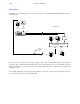
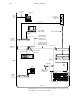
The Thomson automation system can be used for simultaneous control of a Jupiter–controlled router and a Saturn master
control switcher. Two hardware arrangements are possible:
— Option 1: MC 2095 connected to the Jupiter LAN. See page 2–88.
— Option 2: MSL 4000 connected to the Jupiter LAN. See page 2–89.
In either case, the MC 2095 is connected to the MSL 4000 and the MSL 4000 is connected to a VM/SI serial port and
to the Saturn Auto/Log port.
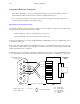
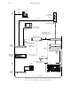
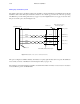
Ready–made cables, with installed 9–pin D and RJ45 male connectors, are available from Thomson. For those who wish
to prepare their own cables, the pin–outs for the Saturn–to–Automation connection are shown in Figure 2–60. The cable
itself should be Belden 8723 or equivalent.
Automation requires no special entries in the Saturn configuration tables. However, a compiled (alphabetically sorted)
version of the Saturn Input set must be entered into the automation computer. For more information, see page 3–46.
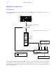
Figure 2–60. Cable for connecting
Saturn to MSL 4000.
1
6
Tx–
2
7
3
Rx–
8
4
9
5
to Saturn Video Processor
Auto/Log port
to MSL 4000
IFS 4
DB9P
(male)
RJ45P
(male)
Rx+ Receive plus
Rx– Receive minus
Tx+ Transmit plus
Tx– Transmit minus
G Ground
Belden 8723 or equivalent
= Shielded, twisted pair
Tx+
Rx+
G
G
to MSL 4000
IFS 4
RJ45P
(male)
Tx+
1
2
3
4
5
6
7
8
Tx–
G
Rx–
Rx+
G
G
G