
Installation manual

2–8 Hardware installation
8. Install Backup Switcher, if one has been supplied. Installation of the AAB 3500/4000 or DAB 3500/4000 backup
switcher involves two main steps:
a. Hardware installation.
The AAB 3500/4000 or DAB 3500/4000 is usually controlled by a CE 300 Control Board mounted inside
the AAB or DAB chassis. The CE 300 is connected via an independent MPK* bus to a control panel. The
chassis with the CE 300A card can be connected to another backup chassis and connected with a crosspoint.
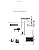
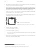
— If the Saturn installation consists of a single system (see Figure 2–3), the backup control panel will con-
sist of the “Select” push buttons on the right side of the Saturn control console.
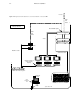
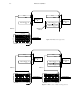
—If the Saturn installation is multi–system (see Figure 2–6), the Select push buttons on the control console
will not be available (they must be used for channel selection). In this case, the backup control panel will
most often be a CP 300, 310, 320, or 330.
For detailed AAB installation information, see page 2–33.
For detailed DAB installation information, see page 2–40.
b. CE 300 Software configuration.
This step is required if alphanumeric mnemonics are desired for display on the “Select” or CP 320 backup
control panel. If this step is not performed, the backup switcher will still operate but the backup control panel
window will display numerics only.
The CE 300 is configured using an application completely outside the normal Saturn/Jupiter menu structure.
This editor, referred to as the “BTS Configuration Editor,” is described in a separate manual entitled CP 300
Series Control Panels / CE 300 Control Board, Thomson part no. 04-045227-002.
For detailed installation information, see page 2–55.
9. Install MCC 3500 / MCS 4000 Control Console(s).
a. Mechanical installation
Cutout dimensions are shown on page 2–61 (MCS 4000) and page 2–62 (MCC 3500).
The control console should be mounted in a desk or table top at the actual master control location. The console
should be angled toward the operator to provide better readability of the displays and front panel markings.
The control console should not be mounted in such a way as to block the ventilation holes on the sides, bottom,
and rear of the chassis.
b. Cabling—see page 2–59.
c. Switch settings
* Terms marked with an asterisk are defined in Glossary at the back of the manual.