
Installation manual

2–76 Hardware installation
Audio Cabling
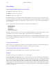
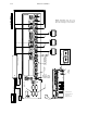
All Saturn audio processors use a plug–in “terminal block” connector scheme (Phoenix Combicon). A mating
connector is supplied with the switcher chassis for each receptacle on the rear panel. (See Figure 2–55.) Each
channel is marked with +, – and G(round) on the plug for connection of balanced audio cables. Wires are connected
by stripping back the insulation 1/4 inch and sliding the bare wire into the connector. A small screwdriver is then
used to tighten the screw on top of the connector and clamp the wire. After the wires are attached, the connector is
plugged into the rear panel of the processor to complete the audio wiring connections.
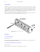
If the processor must be removed from the rack after installation, the audio cable connector plugs can be pulled out
of the rear panel to free the chassis unit without disturbing the original connections.
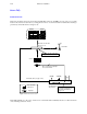
Figure 2–55. Removeable rear panel audio cable
connector detail.
2. SECURE WIRE WITH
SMALL SCREWDRIVER
3. INSERT
CONNECTOR
INTO REAR
PANEL
1. INSERT WIRE
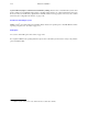
Analog Audio
Systems with Internal Matrix
Please refer to page 2a–1.
In these systems, up to 16 inputs can be connected to the rear panel of Processing Unit on a permanent basis. These are
connected to the left and right matrix inputs IN0 – IN15.
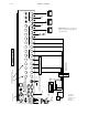
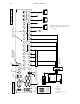
Systems Using External Matrix (Jupiter–Controlled Router)
Please see page 2a–2.
Each analog audio level of the router that is used by the Saturn has five connections: