
Installation manual

2–74 Hardware installation
(NOM.=48V)
LAN
AIR 1
IN 10
ISO 2
IN 2
ALARM ISO 1
IN 1IN 0
KEY 2
IN 6
ISO 4
IN 4
ISO 3
IN 3
KEY 1
IN 5
BKGND B
IN 8
BKGND A
IN 7
BYPASS
IN 9
PGM 1
IN 12
AIR 2
IN 11
PGM 2
IN 13
PVW 1
IN 14
PVW 2
IN 15
BUS INPUTS OUTPUTS
REF
DIGITAL VIDEO
FUSE is located internally
on Digital Video Units
Sync
2
Internal matrix connectors are
covered when option is not installed
Transmitter
to Router
to Saturn audio chassis and control panel(s),
Jupiter File Server, VM–3000 Control System.
LAN
PRESETPROGRAMAIR
Jupiter–controlled
digital video router
CG1
Key (hole)
Video (key fill)
Key (hole)
Video
(key fill)
Video (key fill)
Key (hole)
Still
store
Effects
See note 4
to Router
Automation/
log port
1
Redundant power
supply connector
used on DVP 3500
–21V
+21V
NC
40–60 V
++––
NC
from redundant
power supply
NC
Pin 2
+21V
Pin 3
–21V
21
CLEAN FEED
Clean feed option. Both
outputs same as PGM
output but without Key
inserted in video
To DVE
option
3
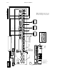
ISO (key hole) inputs 1–4.
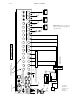
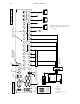
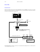
Figure 2–53. Digital video chassis,
showing installation with Jupiter con-
trolled router.
POWER
CONFIG
PROBE
TE
PE
AUTO/LOG
MPK
AUTO SELECT
100–130/200–250V
1.2/0.6A 47–63HZ
DC IN
40–60V 3A
1
See page 2–87.
2
See page 2–70.
3
See page 2–86.
4
See Step 15(a) on page 2–11.
5
See page 2–71.
reference
5
1
0