
Installation manual

Hardware installation2–73
WARNING: FOR CONTINUED PROTECTION
TE
1.0A
220V 0.63A 250V T
AGAINST RISK OF FIRE, REPLACE ONLY
WITH SAME TYPE AND RATING OF FUSE.
115V 1.25A 250V SLOW BLOW
MPK
47–63HZ
PE
200/220/240V
0.5A
POWER
LAN
CONFIG
from
redundant
power supply
4
AIR 1
IN 10
ISO 2
IN 2
ALARM ISO 1
IN 1IN 0
KEY 1
IN 6
ISO 4
IN 4
ISO 3
IN 3
KEY 2
IN 5
BKGND A
IN 8
BKGND B
IN 7
BYPASS
IN 9
PGM 1
IN 12
AIR 2
IN 11
PGM 2
IN 13
PVW 1
IN 14
PVW 2
IN 15
100/120/140V
Transmitter
Jupiter–controlled
analog video router
to
Router
to Saturn audio chassis and control panel(s),
Jupiter File Server, VM–3000 Control System.
LAN
PRESETPROGRAMAIR
to
Router
CG1
Key (hole)
Video (key fill)
Key (hole)
Video (key fill)
Video (key fill)
BUS INPUTS
PROBE
OUTPUTS
+8V
GND
GND
+11V
–11V
AIR GAIN
AIR EQ
PGM GAIN
PGM EQ
PVW GAIN
PVW EQ
ANALOG VIDEO
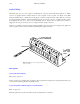
Internal matrix connectors are
covered when option is not installed
See Note
3
Key (hole)
Still
store
Effects
AUTO/LOG
+8V
AGND
+11V
–11V
GND
Automation/log port.
1
Ferrite
bead
ISO (key hole) inputs 1–4.
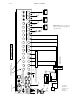
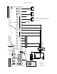
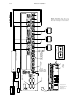
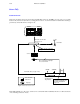
Figure 2–52. Analog video chassis,
showing installation with Jupiter–
controlled router.
1
See page 2–87.
2
See page 2–71.
3
See Step 15(a) on
page 2–11.
4
See page 2–14.
2
1
0