
Installation manual
Hardware installation2–71
Video Cabling
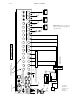
Systems Using External Matrix (Jupiter–Controlled Router)
For Analog video, please refer to page 2–73.
For Digital video, please refer to page 2–74.
For HD video, please refer to page 2–75.
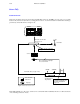
The Saturn accepts video from a Jupiter–controlled routing switcher, processes it, and provides preset, program, and on–
air outputs. The Saturn uses five outputs of the routing switcher. These outputs should generally be successive to maintain
proper timing. On Venus switchers, the outputs must be from the same group (on a Venus switcher, a group usually con-
sists of 32 outputs).
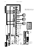
The five outputs of the routing switcher should be connected by equal length cables to:
BKGND INPUT A
BKGND INPUT B
KEY INPUT 1
KEY INPUT 2
BYPASS VIDEO INPUT
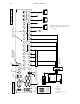
The Saturn outputs are generally connected to monitors, distribution amplifiers, or into the routing switcher to provide
for distribution to the rest of the system. The AIR 1 output should be fed to the transmitter chain.
The Digital Video and HD Video Processors can optionally include two identical “clean feed” outputs. These are always
the same signal as the PGM output, except that no key insert video is ever included. For installation diagrams, see pages
2–74, 2–75, and 2–86.
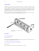
Systems Using Internal Matrix
In these systems, up to 16 inputs can be connected to the rear panel of Processing Unit on a permanent basis. These are
the connectors labelled “IN0” through “IN15.” See pages 2–73 (analog) and 2–74 (digital).
Systems Using Both External Router and Internal Matrix
Systems equipped with the internal matrix can also use the five router connections if desired.
ISO Inputs
The Saturn provides up to four external key hole cutter (“ISO”) inputs.
Systems with Jupiter–controlled router – These systems are capable of auto key routing. The first two ISO inputs can
be connected to the Jupiter–controlled routing switcher, either to the main video matrix, or to a separate key matrix. This
allows selection of an external key signal from any source feeding the router. When KEY 1 is in external key mode, it
always uses the hole cutter coming into the ISO 1 input; KEY 2 always uses ISO 2 input for external key mode. ISO 3
and ISO 4 inputs are not used for auto routing (but can be used for manual key routing as described below). When properly
configured, Saturn provides an automatic switch to the correct key hole signal for the selected key fill. For configuration
instructions, see page 3–58.