
Installation manual

2–68 Hardware installation
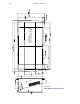
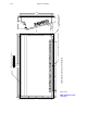
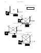
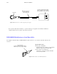
Audio Metering Cable
The Saturn Master Control Switcher system uses an enhanced high–speed RS–485 serial cable to distribute meter data
from the various system audio processors to one or more master control operator consoles and external meter bridges.
(See Figure 2–49).
CONTROL ROOM 1 CONTROL ROOM 2 TRANSMISSION
MCC OPERATOR
CONTROL PANEL
MCC OPERATOR
CONTROL PANEL
MCC OPERATOR
CONTROL PANEL
EQUIPMENT RACK A EQUIPMENT RACK B
SYSTEM 1 ELECTRONICS SYSTEM 4 ELECTRONICS
SYSTEM 2 ELECTRONICS SYSTEM 5 ELECTRONICS
SYSTEM 3 ELECTRONICS SYSTEM 6 ELECTRONICS
AAP/DAP AAP/DAP
AAP/DAP AAP/DAP
AAP/DAP AAP/DAP
AAP/DAP AAP/DAP
AAP/DAP AAP/DAP
AAP/DAP AAP/DAP
METER METER
METER
METER
METER
METER
METER
METER
METER
METER
METER
METER
TERMINATOR
METER METER METER
Figure 2–49. Saturn audio metering cable (example).
MCM EXTERNAL
METER BRIDGE
TERMINATOR
MCM EXTERNAL
METER BRIDGE
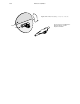
The metering cable uses a standard SMPTE DB–9 pinout with male pins on the cable connectors. High quality dual
shielded–pair cable should be used throughout the system. (For a cable assembly drawing, see Figure 2–48 on page
2–67.)
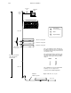
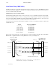
The Saturn audio metering cable is based on the RS–485 data interconnection standard but must be terminated at each
end with externally powered ALT 3500 Audio LAN Terminators (part no. F7–020200–024). The ALT 3500s force the
noise margins to be higher, and “pull” the RS–485 network to known states when no transmitters are enabled on the LAN.
These terminators should be placed at the ends of the LAN and plugged into 110 volt 60 Hz power.
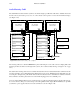
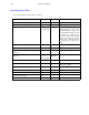
Users in countries utilizing different power systems may have to replace the wall–mount plug–in supplies with appropri-
ate ones for their area. The power sources must provide well regulated 5 VDC output (100 mA minimum), two per LAN
system. These power supplies must be wired to the terminators as shown in Figure 2–50.