
Installation manual

Hardware installation2–67
Serial Data Cabling (MPK Cables)
The RS–422 cables used to connect the console and other devices to the video processor (or other MPK device) may be
known by various names (“MPK bus,” “serial cable,” etc.) In spite of the different terminology, each of these buses con-
sist of a 4–conductor (plus ground) cable.
Maximum length per bus is 1220 meters (4003 ft).
The back panel serial data cable connectors on the console, video processor, and backup switcher are 9–pin D, female.
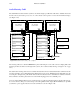
The console, MI 3040, and SD 3x connectors are arranged for loop–through wiring. No termination is required. While
these connectors are ESbus compatible, it should be noted that the Thomson serial data cables use only 5 of the 9 pins
described in the ESbus specification (see Jupiter Install/Operate manual Appendix).
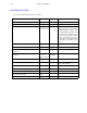
The following ready–made cables, with installed 9–pin D male connectors, are available from Thomson (VDE* cables
include ferrite cores):
Length Part no. for VDE cable
1 meter (3.3 ft) 01–041600–001
2 meters (6.6 ft) 01–041600–002
4 meters (13.1 ft) 01–041600–004
8 meters (26.2 ft) 01–041600–008
16 meters (52.5 ft) 01–041600–016
32 meters (105 ft) 01–041600–032
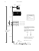
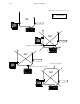
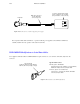
For those who wish to prepare their own cables, the pin–outs are shown in Figure 2–48. The cable itself should be
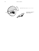
Belden 8723 or equivalent. Details concerning VDE ferrite cores are given in Figure 2–51.
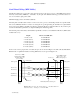
Video Processor MPK,
Backup Switcher MPK,
and Audio Meter ports
(bus controller)
Console MPK and Audio
Meter ports or other
MPK control panel port
Figure 2–48. Serial data cable wiring. Reference: “Assembly, BCS 3000
Serial Data Cable,” drawing no. 01–039806–TAB.
1
2
3
7
8
1
2
8
P1
DB9P
(male)
Shield (drain)
Green
Black
White
P2
DB9P
(male)
3
7
Red
Frame ground
Receive A (–)
Transmit A (–)
Receive B (+)
Transmit B (+)
Transmit B (+)
Transmit A (–)
Receive B (+)
Receive A (–)
Frame ground
Individually shielded, twisted pairs
Ferrite core
Green
Black
White
Red
Ferrite core
*see Glossary.