
Installation manual

2–6 Hardware installation
6. The switcher Processing Units (and redundant power supply) should be mounted in a rack or other suitable enclo-
sure that provides power and cooling facilities for the equipment.
The Processing Units are designed for mounting in a standard 19–inch wide equipment rack having a depth of 24
–30 inches. Rear support is recommended, especially in a remote equipment truck or in other locations subject to
vibration and stress. When the Saturn is installed with a Thomson Crosspoint Bus* routing switcher, the Processing
Units should be mounted near the router because of the number of cables interconnecting the two units.
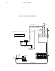
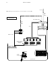
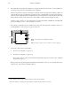
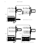
A Saturn “system” consists of one video channel and its associated audio channels.§ Installations can include multi-
ple systems, multiple consoles, or both. See Figures 2–6 and 2–7.
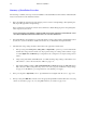
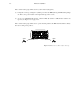
Proper attention should also be given to ventilation and cooling of the Processing Units. See Figure 2–5. For corre-
sponding illustrations of the console, see pages 2–62 and 2–59.
Front
Figure 2–5. Typical air flow pattern for Saturn rack mount equipment.
22 inches
= area to keep clear of obstructions to airflow
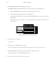
7. Connect the required video and audio cables:
a. For video processing units, see page 2–71.
b. For audio processing units, see page 2–76.
The “Config” connector on the rear of the Audio Processing Unit(s) can be used to activate a stereo synthesizer
if desired. See page 2–77.
During operation, any input feeding the external matrix, the Direct Input connectors, or the internal matrix can be
assigned to any of the sixteen Program/Preset buttons.
* Terms marked with an asterisk are defined in Glossary at the back of the manual.
§ The term “channel” is sometimes used in the Saturn user interface in place of the word “system.”)