
Installation manual

Hardware installation2–57
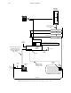
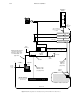
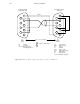
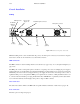
Figure 2–40. Switcher to AT–type computer cable. Reference: part no. 01–044827–001.
1
6
Rx
2
7
3
Tx
8
4
9
5
1
6
Rx
2
7
Tx
3
8
4
9
LG
5
to AAB–3500/4000
Configuration Port
to AT–type Computer
Serial Port
Rx Receive
Tx Transmit
4–6–9 Jumpered together;
internally grounded
P1
DB9P
(male)
P2
DB9S
(female)
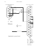
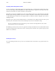
Shield
CD Carrier detect
DSR Data set ready
Rx Receive
Tx Transmit
CTS Clear to send
DTR Data terminal ready
RI Ring indicator
LG Logic ground
1–4–6–8–9 Jumpered together
50 ft ( 15.2 m) maximum
= twisted , shielded pair
LG
G
G
G
CD
DSR
CTS
DTR
RI