
Installation manual
2–56 Hardware installation
i. The Panel Assignments tables will normally be left blank (i.e., so that the panel will control the output as-
signed via the panel’s DIP switch).
However, if for some reason one of these tables needs to be used (to override the DIP switch setting), please
note that the CP 300/330 table will be used by the Select button group; in which case “Poll 0” on this table
will actually correspond to Polling Number 60, “Poll 1” will correspond to Polling Number 61, etc. See Figure
2–37 on page 2–52.
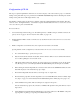
Select Button Group Diagnostics
To enter the diagnostic mode for the panel, while holding the first button (button 1) down, also push the last button (button
15) down. Button 1 and Button 11 will light so that the desired diagnostic can be selected. Button 1 will perform the
button/lamp Test. Press any button twice to exit this test. Button 11 will perform the VF Display Self–test. Pressing any
button twice will exit this test. To perform the lamp self test, disconnect the panel from the MPK bus.
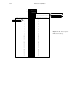
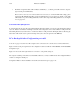
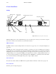
PC to Backup Switcher Configuration port cable
As shown on pages 2–53 and 2–54, a PC computer can be connected to the control board to download mnemonics.
Figure 2–40 shows the pin assignments for the configuration cable used with the AAB 3500/4000 or DAB 3500/4000
Configuration port.
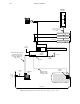
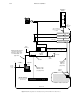
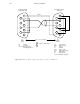
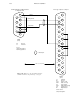
Figure 2–41 shows the cable requirements for connection to a 25–pin PC serial port.
The computer’s COM1 port should be used if available. Otherwise, connect to COM2 and use the Configuration Editor
software to change the default port.
Configuration Editor Software installation and download instructions begin on page 2–55.